
What Is the Best Molded Circuit Breaker for 2026?
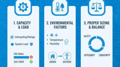
Choosing the best Molded Circuit Breaker for 2026 starts with the equipment it must protect, not a brand ranking. A breaker in a compact control panel may face different demands from one serving a large motor or a building’s main distribution board. Rated current, voltage, number of poles, and interrupting capacity all need to match the installation. Not quite a one-size choice.
Trip-unit options matter, too. Thermal-magnetic protection may suit straightforward circuits, while electronic trip units can offer adjustable settings and clearer fault information. Check the manufacturer’s published ratings and coordination guidance, then compare them with the system’s available fault current. A breaker that fits the rail but cannot safely interrupt a prospective fault is not the right fit. Small details matter.
This guide looks at practical selection factors, including application, protection settings, operating conditions, and service needs. For example, heat inside a tightly packed enclosure can affect performance, while frequent switching may call for features beyond basic overload protection. It also considers how documentation, accessories, and technical support influence long-term ownership. The strongest choice is usually the one that meets the actual design requirements and is supported by verifiable specifications—not simply the model with the longest feature list. Even careful comparisons have limits: product data may differ by configuration, and a tidy table can hide important exceptions. Confirm details for the exact model before making a decision.
Define MCCBs by IEC 60947-2’s 1,000 V AC and 1,500 V DC limits
What Is the Best Molded Circuit Breaker for 2026?
Define MCCBs by IEC 60947-2’s 1,000 V AC and 1,500 V DC limits
An MCCB is a molded-case circuit breaker, but its name alone does not define its voltage capability. IEC 60947-2 covers circuit breakers intended for circuits up to 1,000 V AC or 1,500 V DC. These are standard limits, not a promise that every MCCB operates at either maximum. Check the specific device’s rated voltage and application data.
That distinction matters. A breaker selected for a 690 V AC panel, for example, should have a suitable AC rating and fault-interruption capacity for that installation. DC systems need particular care: interrupting a DC fault can be challenging because the current does not naturally pass through zero. Verify the manufacturer’s DC ratings, pole configuration, and connection instructions rather than assuming an AC rating carries over. Also compare rated current, trip settings, and short-circuit performance with the actual system. The best choice depends on the job, not a single headline number. A datasheet can still leave room for interpretation, so confirm the exact circuit conditions before specifying a device.
Compare rated current, frame size, and interrupting capacity in kA
Choosing the best molded-case circuit breaker for 2026 starts with the load, not the frame label. Rated current should match the circuit’s expected operating current and account for continuous loads, ambient temperature, and conductor limits. A 250 A feeder, for example, might use a breaker with a 250 A trip rating, but the actual choice depends on the installation and applicable design requirements. Check the trip unit settings, too. A large frame does not automatically mean a higher usable current.
Frame size describes the breaker’s physical platform and its general current range; it is not the same as rated current. Interrupting capacity, shown in kA, indicates how much fault current the breaker can safely interrupt at a specified voltage. Compare that rating with the available short-circuit current at the installation point. It must be adequate there. Also verify the voltage rating and coordination with upstream and downstream protection. Small details matter.
There is no perfect shortcut. A breaker that fits the load may still have insufficient interrupting capacity, while an oversized frame may add cost without improving protection. I would confirm site fault-current data and manufacturer documentation before specifying a device. Estimates can be wrong. That deserves a second look.
Match trip curves and protection settings to load and fault conditions
What Is the Best Molded Circuit Breaker for 2026?
The best molded case circuit breaker is the one whose trip behavior fits the actual load and available fault current. A motor may draw a brief starting surge, while a heater usually presents a steadier load. Choose a trip curve that tolerates normal startup without allowing damaging overloads to persist. Small details matter.
Check the equipment nameplate, conductor capacity, ambient temperature, and expected operating cycle before setting protection. A breaker’s long-time setting should protect the conductors, not merely keep a machine running. Short-time and instantaneous settings also affect how quickly faults clear and whether upstream devices trip unnecessarily. Coordination can be tricky.
For example, a compressor starting beside other equipment may need different settings from a lighting panel with predictable loads. Compare the breaker’s interrupting rating with the prospective fault current at its installation point. Do not raise a setting simply to stop nuisance trips; the cause may be inrush, wiring, or a faulty load. This is where selection gets less tidy. Verify settings against the breaker’s published trip data and applicable installation requirements, with a qualified electrical professional reviewing the design. A careful check now can prevent a trip curve from being either too sensitive or too forgiving.
What Is the Best Molded Circuit Breaker for 2026? - Match trip curves and protection settings to load and fault conditions
There is no single best molded-case circuit breaker (MCCB) for every installation. Use the load and fault conditions below as preliminary selection guidance, then verify the final device and settings against the applicable electrical code, equipment ratings, coordination study, and manufacturer time-current curves.
| Application / load | Typical trip unit | Long-time overload guidance | Short-time / instantaneous guidance | Ground-fault protection | Key selection check |
|---|---|---|---|---|---|
| General lighting and receptacle feeder Relatively steady, mixed loads |
Thermal-magnetic for simple systems; electronic LSI where adjustable coordination is needed | Set or select the rating to protect the conductors and account for continuous-load requirements. Do not exceed conductor ampacity after applicable corrections. | Use a standard inverse-time characteristic. Choose instantaneous pickup high enough to avoid nuisance trips from normal inrush, but low enough to clear faults promptly. | Use when required by code, system design, or equipment needs; coordinate pickup and delay with downstream devices. | Check conductor ampacity, downstream selectivity, available fault current, and the breaker's interrupting rating at the actual system voltage. |
| Induction-motor branch circuit High starting current and repeated starts |
Thermal-magnetic or electronic; a separate motor overload device is commonly used for motor overload protection. | Coordinate the breaker with the motor overload relay and applicable motor-circuit rules. Do not rely on a short-circuit trip unit alone to protect a motor from sustained overload. | Allow for measured or documented starting current and acceleration time. Electronic instantaneous settings are application-specific; confirm against the motor start profile and fault-clearing requirements. | Usually determined by the distribution system and code requirements; check compatibility with the motor circuit and downstream protection. | Review motor full-load current, locked-rotor current, starting method, starts per hour, cable protection, and the motor protection coordination study. |
| Transformer secondary or distribution feeder Possible inrush and downstream fault contribution |
Electronic LSI or LSIG for adjustable time delays and coordination; thermal-magnetic may suit simpler installations. | Set long-time pickup to protect the feeder conductors and stay within the permitted equipment rating. Allow for transformer loading without exceeding the protected conductor limits. | A short-time delay may improve coordination with downstream breakers. Check transformer energization inrush and ensure the delay does not compromise equipment or conductor protection. | Consider LSIG ground-fault protection where required or appropriate; coordinate its pickup and delay with downstream ground-fault devices. | Calculate prospective fault current at the installation point. Confirm interrupting rating and short-time withstand/coordination capability for the specific device. |
| Generator-fed distribution Fault current may be lower and decay over time |
Adjustable electronic LSI or LSIG is often useful where settings must be matched to generator characteristics. | Base pickup on generator, conductor, and load limits. Confirm the generator can carry expected load and that the trip unit responds appropriately to its fault-current profile. | Verify that minimum generator fault current is sufficient to operate the selected short-circuit protection within required clearing times. Avoid settings copied from a utility-fed system without study. | Coordinate with the generator neutral-grounding arrangement and system grounding design; ground-fault sensing and settings depend on that arrangement. | Use generator subtransient/transient data and a protection study. Check both maximum and minimum fault current, including operating modes and source transfer conditions. |
| HVAC compressor or other cycling load Frequent starts, possible elevated starting current |
Thermal-magnetic or electronic trip unit selected for the equipment and branch-circuit requirements. | Follow the equipment nameplate and applicable code provisions. Coordinate the breaker with any specified maximum overcurrent protection and conductor ampacity. | Check compressor locked-rotor current and starting behavior. Confirm the time-current curve tolerates normal starts while still providing short-circuit protection. | Apply where required by the system design or code; coordinate with any equipment-level protection. | Use the actual equipment nameplate and installation instructions; account for ambient temperature, enclosure conditions, and repeated cycling. |
Important: The guidance is indicative, not a set of universal trip values. Final settings must be checked against conductor and equipment limits, prospective short-circuit current, system voltage, grounding method, and coordination requirements. An MCCB’s interrupting rating must be adequate for the available fault current at its point of installation.
Check endurance, selectivity, and coordination with upstream devices
A molded-case circuit breaker should be judged by more than its interrupting rating. Check endurance records for mechanical operations and electrical switching under the intended load; IEC 60947-2 defines the relevant test framework for low-voltage circuit breakers. Ask for the test conditions, not just a pass mark. Were the tests performed at the actual operating voltage and current? A breaker in a warm, crowded panel may age differently from one in a cool test room. Small detail. Big consequence.
Selectivity matters when a fault occurs. Ideally, the downstream breaker trips first, keeping unaffected circuits energized. Compare time-current curves at both overload and short-circuit levels, then confirm the available fault current against each device’s interrupting capacity. Check coordination tables or verified test reports for the exact upstream and downstream combination; similar-looking curves alone do not prove selectivity. The U.S. Energy Information Administration’s 2022 reliability data reported roughly 5.5 hours of average customer interruption, including major events. That figure is not a breaker-performance measure, but it illustrates why limiting an outage’s reach matters. I would still question a perfect-looking study if it omits cable impedance, settings, or the installed upstream device. Real panels are rarely as tidy as drawings. (Sources: IEC 60947-2; U.S. EIA, Form EIA-861 reliability data.)
Choose the best 2026 MCCB by certification, application, and total cost of ownership
What Is the Best Molded Circuit Breaker for 2026?
Choose an MCCB by matching its certification, application, and lifetime cost—not by purchase price alone. Check that its UL 489 or IEC 60947-2 certification, voltage rating, and interrupting capacity fit the installation. Ratings matter.
The IEA’s Electricity 2025 report says global electricity demand rose 4.3% in 2024 and is forecast to grow by an average 3.3% annually through 2027. Growing loads make careful coordination and reliable protection especially important in facilities adding equipment or expanding capacity.
Start with the real operating conditions: available fault current, ambient temperature, load profile, enclosure, and maintenance access. Then compare total cost of ownership, including installation, testing, replacement parts, downtime, and any energy losses. Ask for test documentation and confirm that the breaker coordinates with upstream and downstream devices.
A tidy spreadsheet can still miss the cost of an outage—or assume maintenance that never happens. It is worth challenging those assumptions. The best choice is the model that meets verified site requirements and remains supportable over its service life.
Related Posts
-
2026 Best Molded Case Breaker Types for Buyers?
-
What Are the Top Molded Case Breaker Types in 2026?
-
2026 Best Molded Breaker Types for Global Buyers
-
7 Tips to Choose the Right MCCB Molded Case Circuit Breaker
-
Top 10 MCCB Breaker Manufacturers for Global Buyers
-
How to Choose the Right Molded Case Breaker for Your Needs?

JCB1-125
JCB2-40M
JCB3-63DC
JCB3-80H
JCB3-80M
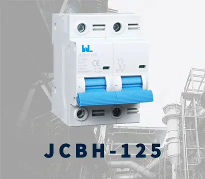
JCBH-125
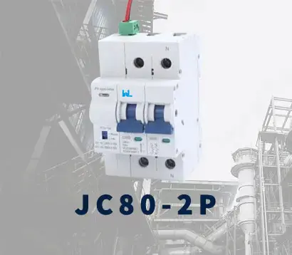
JC125-4P
JCMX
JCSD
JCOF
JCMX1-125

JCOF1-125
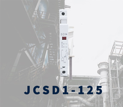
JCSD1-125
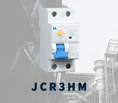
JCR3HM
JCRD2-125
JCRD4-125
JCRB2-100
JC3RH-2P
JC3RH-S
JC3RH-B
JC3RH-BS
JCR2-63
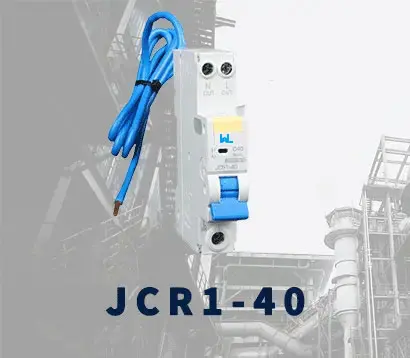
JCR1-40
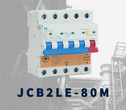
JCB2LE-80M
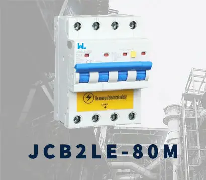
JCB2LE-80M
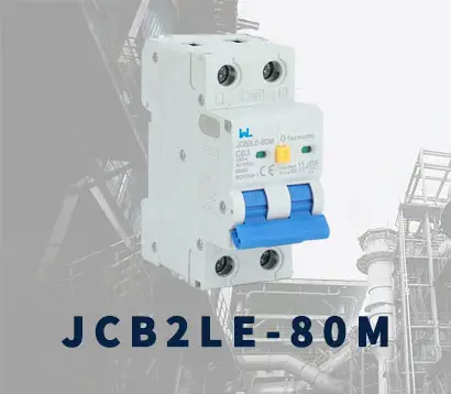
JCB2LE-80M
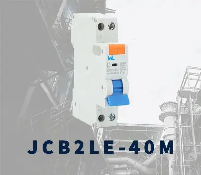
JCB2LE-40M
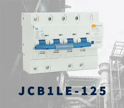
JCB1LE-125
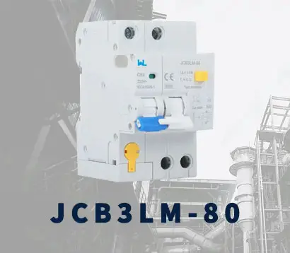
JCB3LM-80
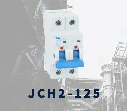
JCH2-125
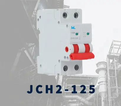
JCH2-125
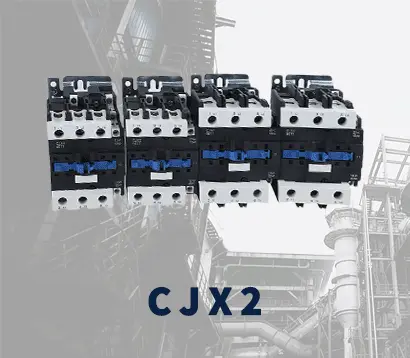
CJX2
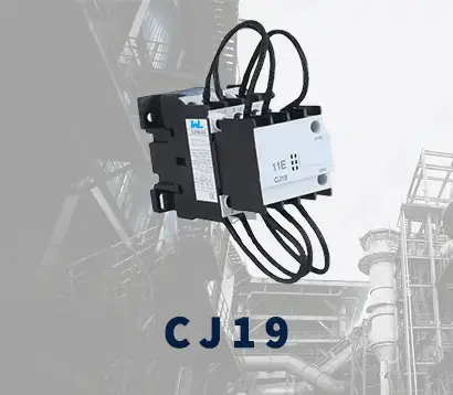
CJ19
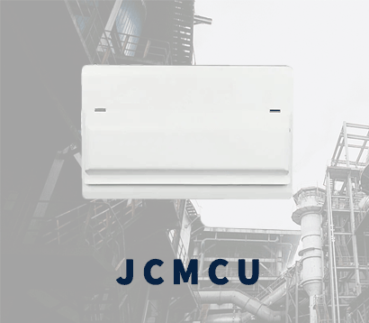
JCMCU

JCHA

JCSD-40

JCSD-60
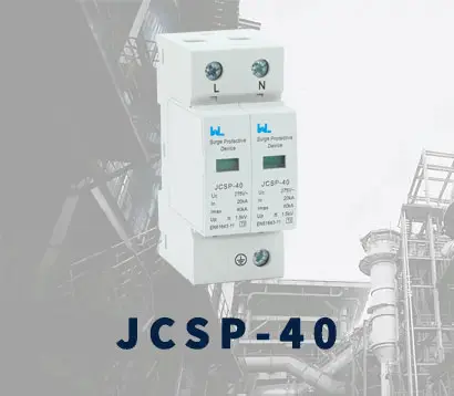
JCSP-40

JCSP-60
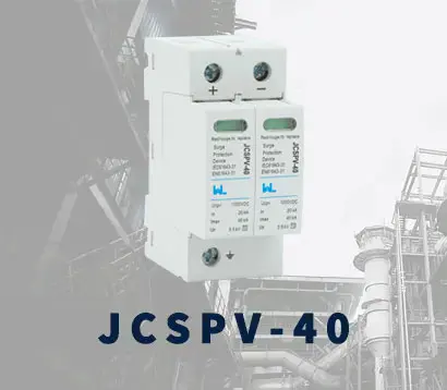
JCSPV
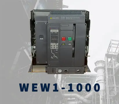
WEW1-1000
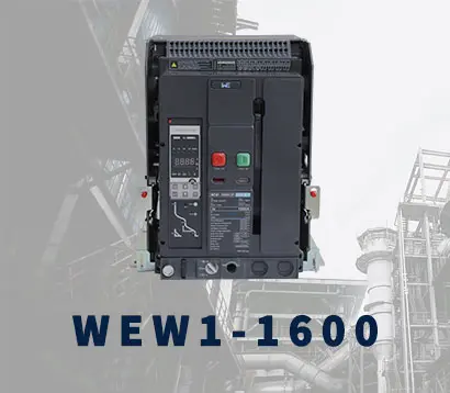
WEW1-1600
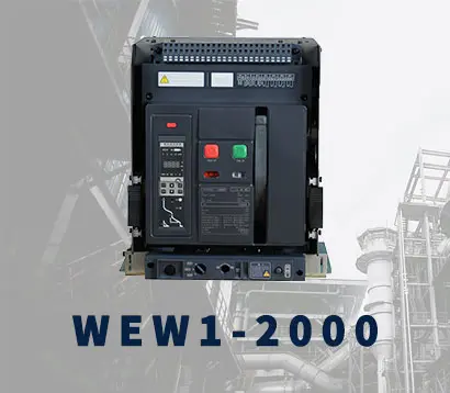
WEW1-2000
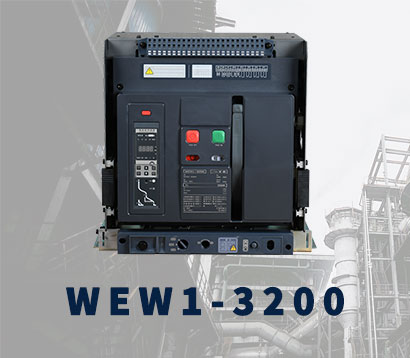
WEW1-3200
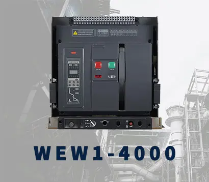
WEW1-4000
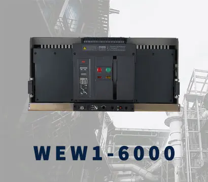
WEW1-6300
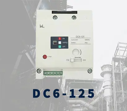
DC6-125
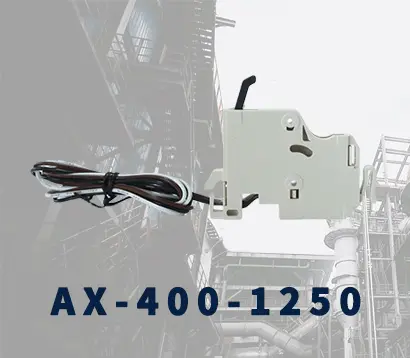
AX-400-1250
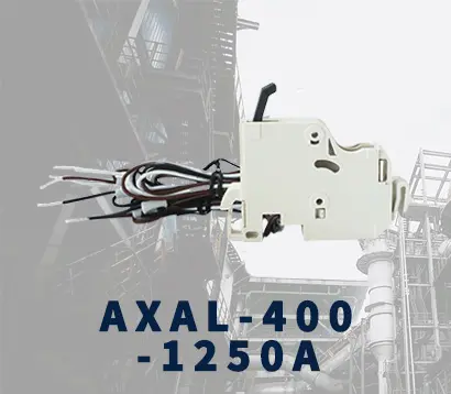
AXAL-400-1250A
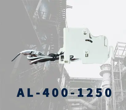
AL-400-1250
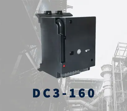
DC3-160
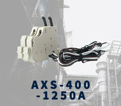
AXS-400-1250A
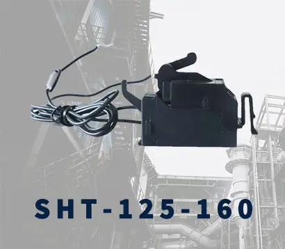
SHT-125-160
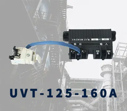
UVT-125-160A

P-250A-3P-A
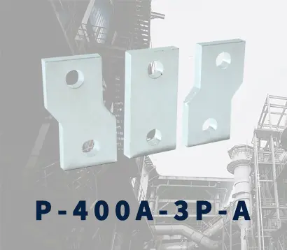
400-3P/4P terminal cover
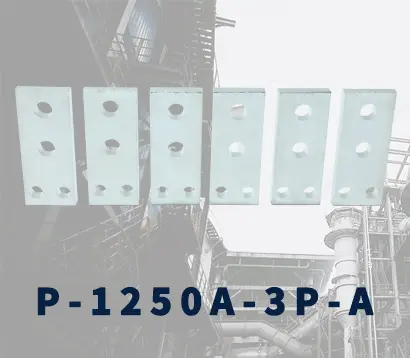
1250-3Pmccb accessories busbar
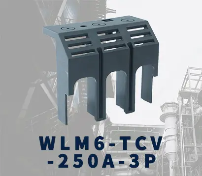
250-3P terminal conver
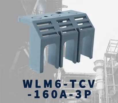
WLM6-TCV-160A-3P
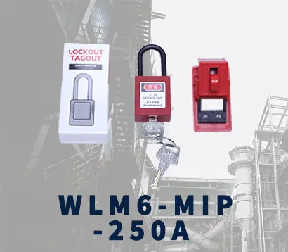
WLM6-MIP-250A
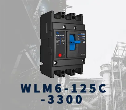
WLM6-125A-3300 3P/4P
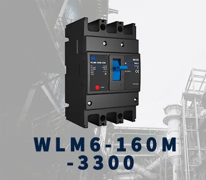
WLM6-160A-3300 3P/4P
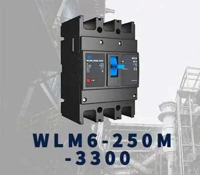
WLM6-250A-3300 3P/4P
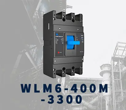
WLM6-400A-3300 3P/4P
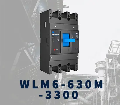
WLM6-630A-3300 3P/4P
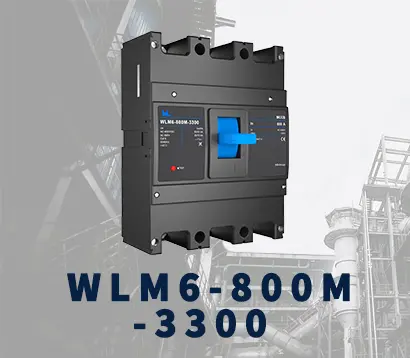
WLM6-800A-3300 3P/4P
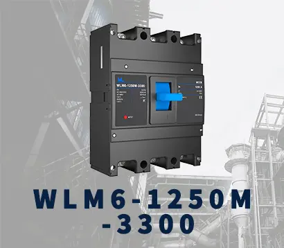
WLM6-1250A-3300 3P/4P
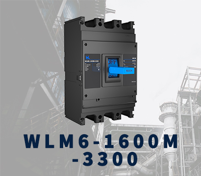
WLM6-1600A-3300 3P/4P
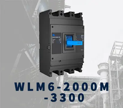
WLM6-2000A 3P/4P
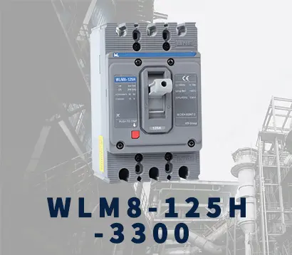
WLM8-125H-3300
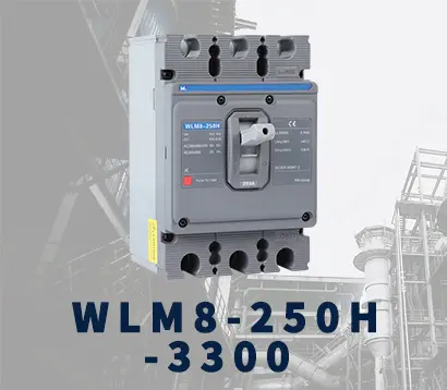
WLM8-250H-3300
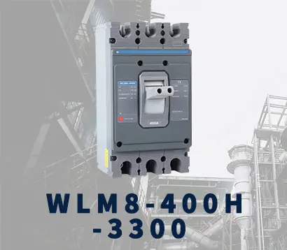
WLM8-400H-3300
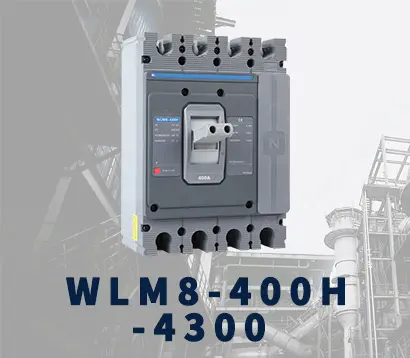
WLM8-400H-4300
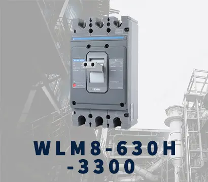
WLM8-630H-3300
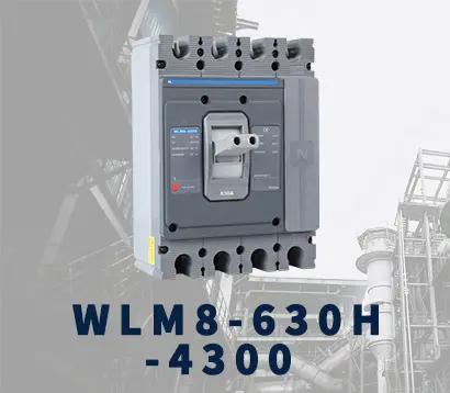
WLM8-630H-4300
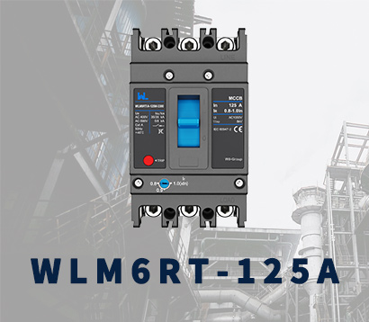
WLM6RT-125A
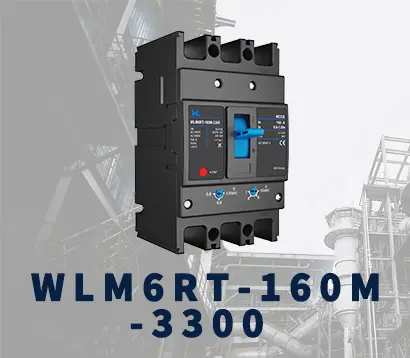
WLM6RT-160A
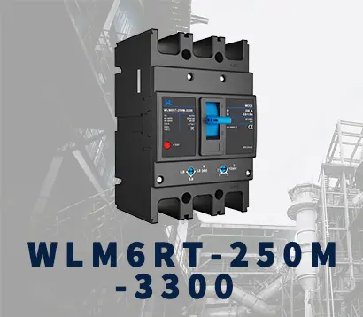
WLM6RT-250A
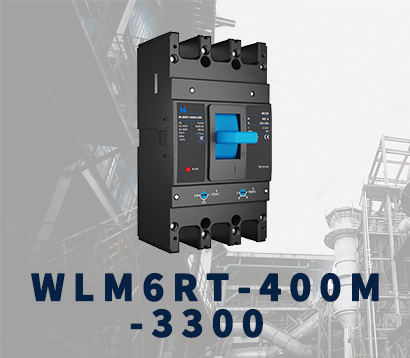
WLM6RT-400A
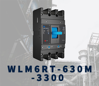
WLM6RT-630A
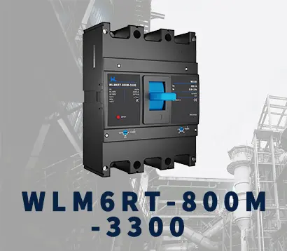
WLM6RT-800A
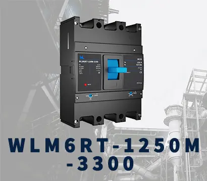
WLM6RT-1250A
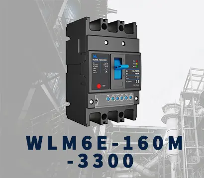
WLM6E-160A-3300 3P
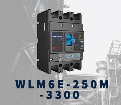
WLM6E-250A-3300
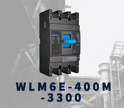
WLM6E-400A-3300 3P/4P
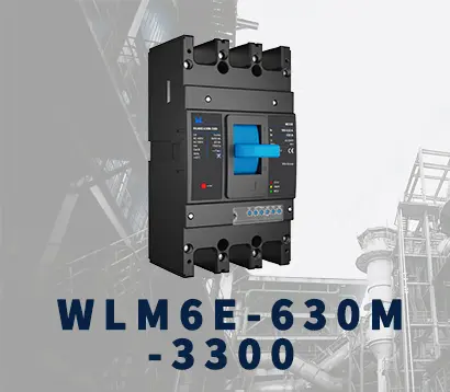
WLM6E-630A-3300
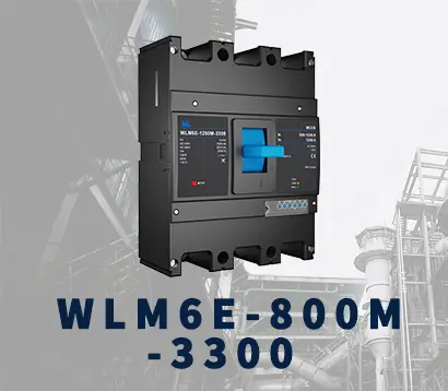
WLM6E-800A-3300 3P/4P
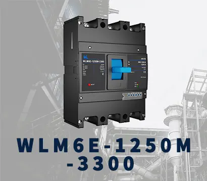
WLM6E-1250A-3300
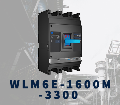
WLM6E-1600-3300 3P/4P
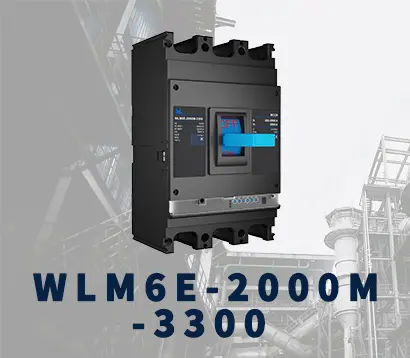
WLM6E-2000A-3300 3P/4P
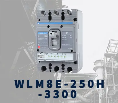
WLM8E-250H-3300
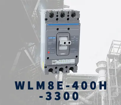
WLM8E-400H-3300
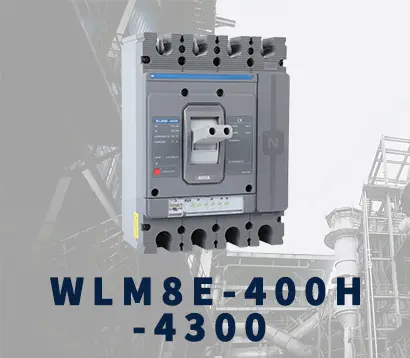
WLM8E-400H-4300
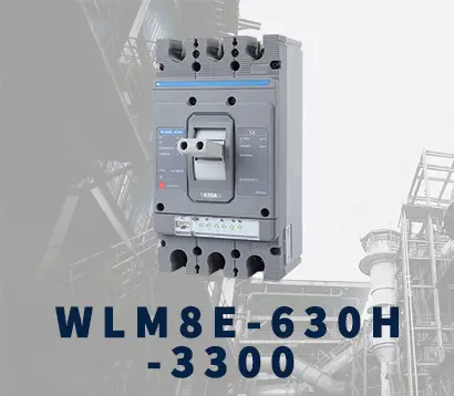
WLM8E-630H-3300
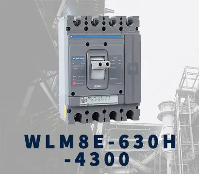
WLM8E-630H-4300
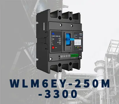
WLM6EY-250-3300 3P/4P
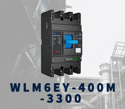
WLM6EY-400 3P/4P
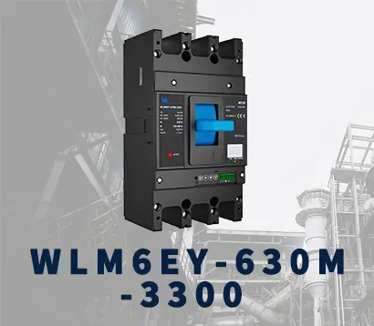
WLM6EY-630 3P/4P
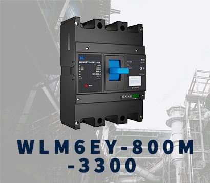
WLM6EY-800A 3P/4P
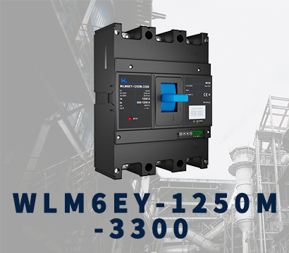
WLM6EY-1250A 3P/4P
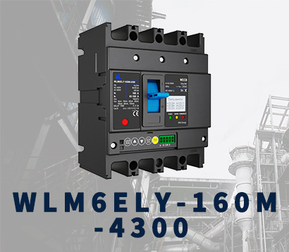
WLM6ELY-160A
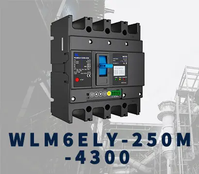
WLM6ELY-250A
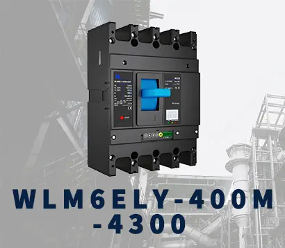
WLM6ELY-400A
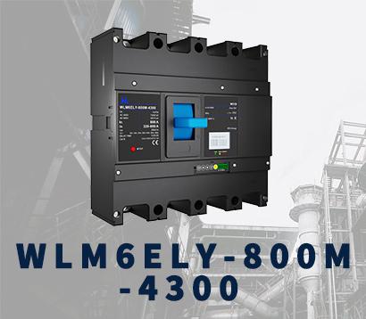
WLM6ELY-800A
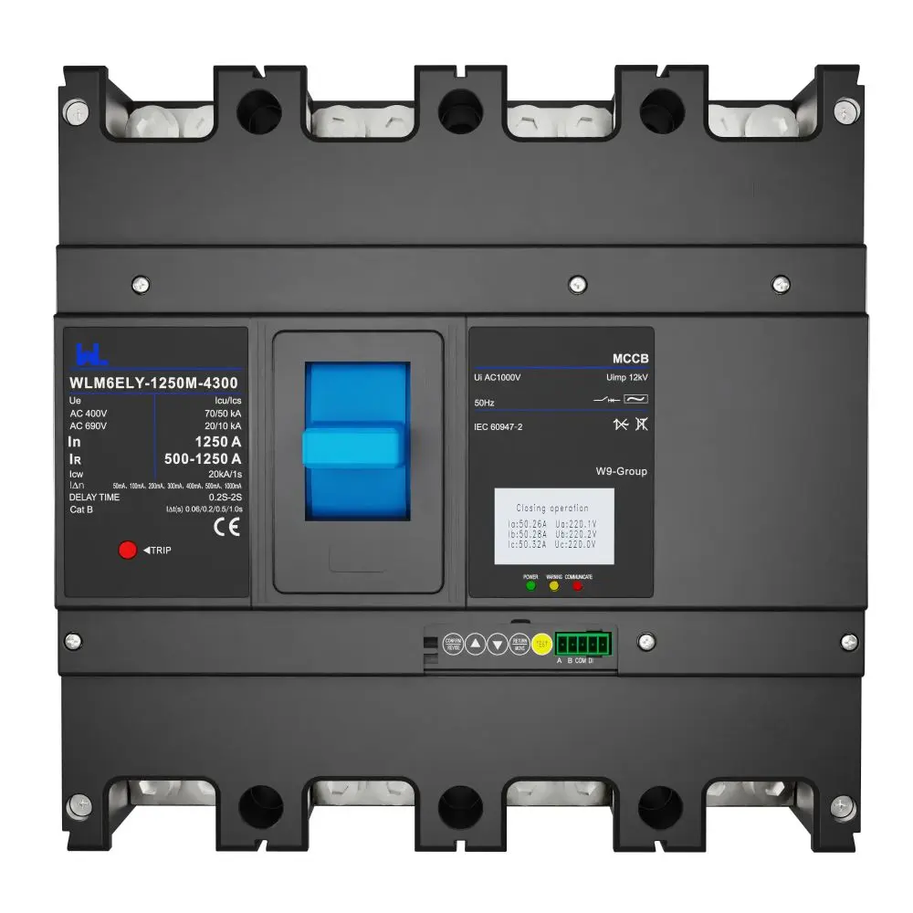
WLM6ELY-1250A
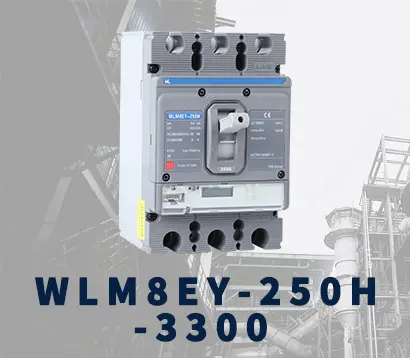
WLM8EY-250H-3300
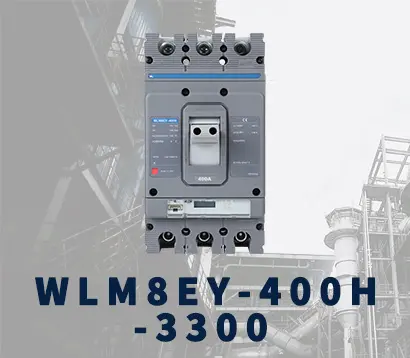
WLM8EY-400H-3300
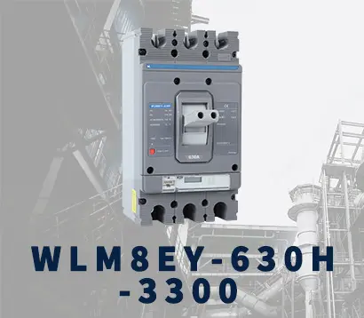
WLM8EY-630H-3300
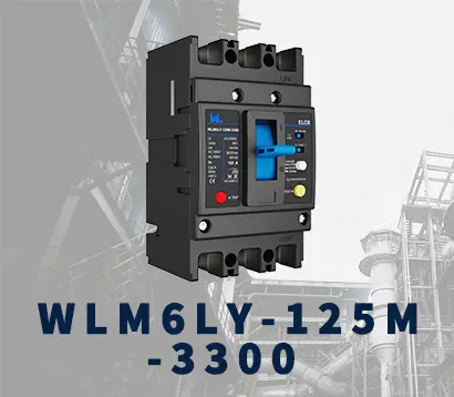
WLM6LY-125A
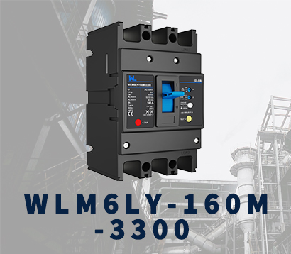
WLM6L-160A
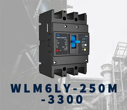
WLM6LY-250A
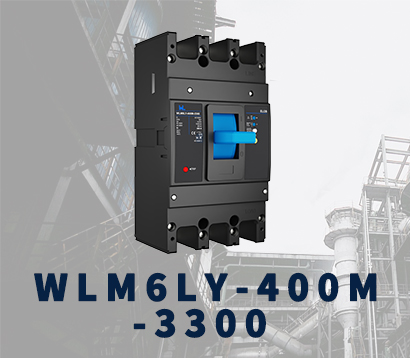
WLM6LY-400A
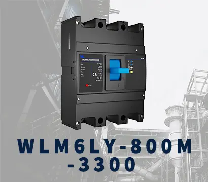
WLM6LY-800A
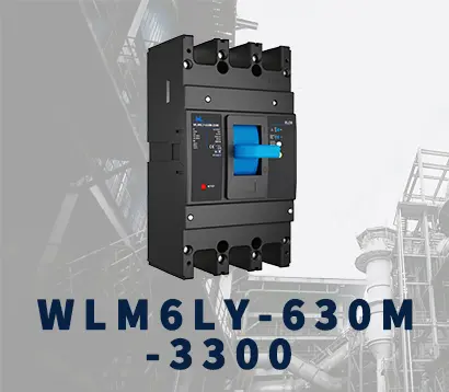
WLM6LY-630A
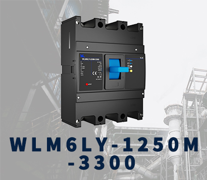
WLM6LY-1250A
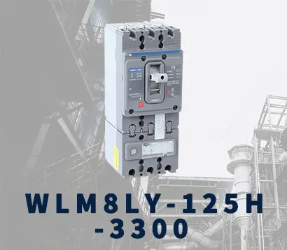
WLM8LY-125H-3300
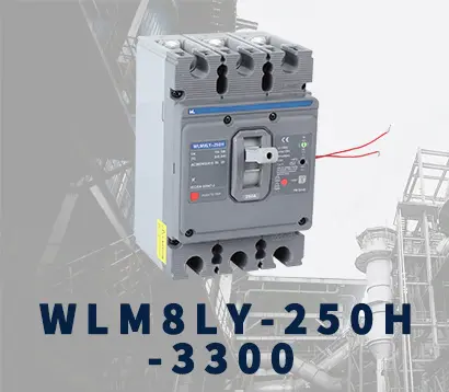
WLM8LY-250H-3300
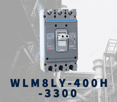
WLM8LY-400H-3300
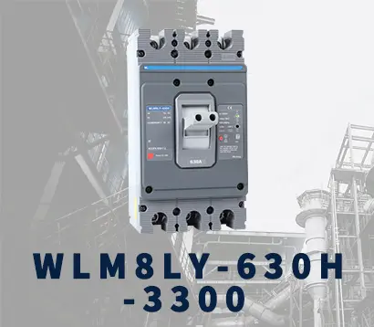
WLM8LY-630H-3300
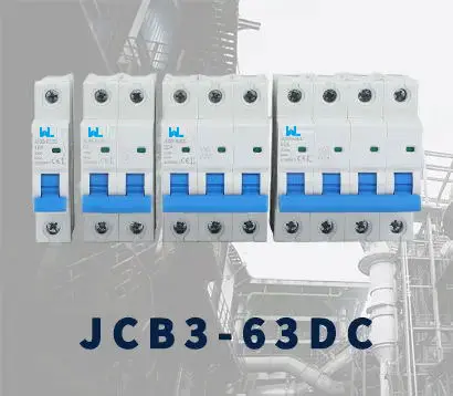
JCB3-63DC
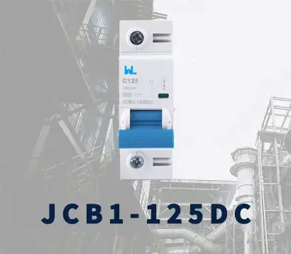
JCB1-125DC
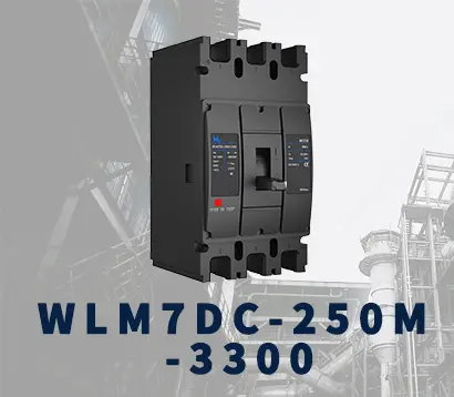
WLM7DC-250A-2300 2P/3P
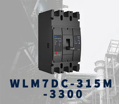
WLM7DC-315A-3300 2P/3P
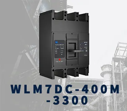
WLM7DC-400A-2300 2P/3P
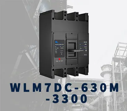
WLM7DC-630A-3300 3P
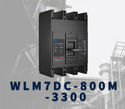
WLM7DC-800A-2300 2P/3P
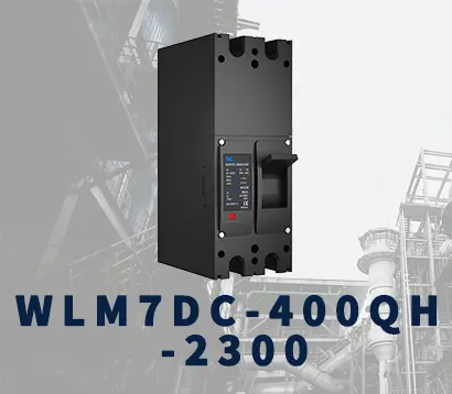
WLM7DC-400A 2300
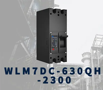
WLM7DC-630A-2300 2P
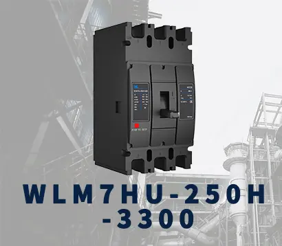
WLM7HU-250-3300 3P
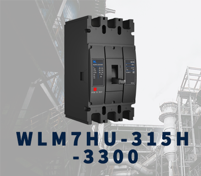
WLM7HU-315-3300 3P
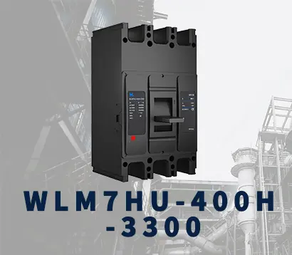
WLM7HU-400-3300 3P
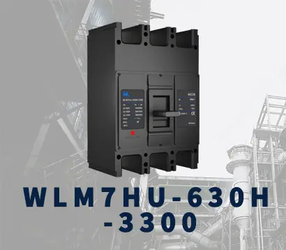
WLM7HU-630-3300 3P
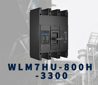
WLM7HU-800-3300 3P
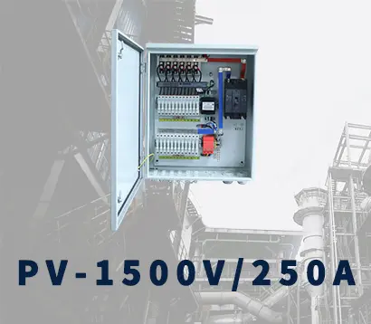
PV-1500V/250A
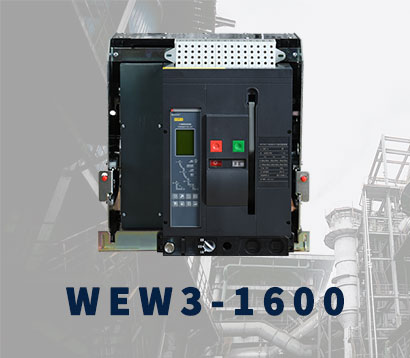
WEW3-1600
WEW3-2500
WEW3-4000
WEW3-7500