
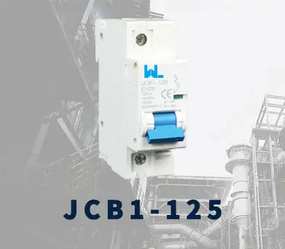
 JCB1-125
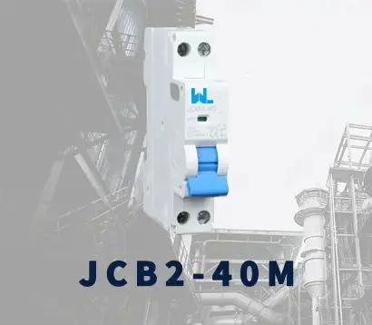 JCB2-40M
 JCB3-63DC
 JCB3-80H
 JCB3-80M
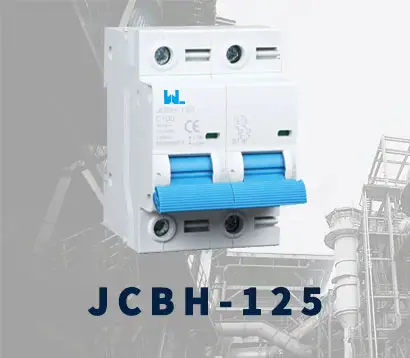 JCBH-125
 JC80-2P
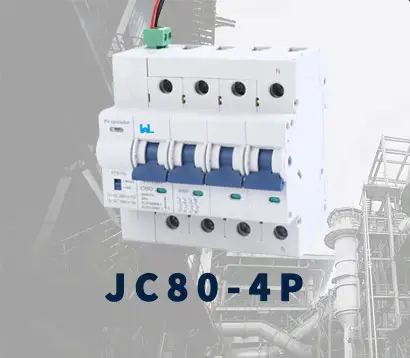 JC80-4P
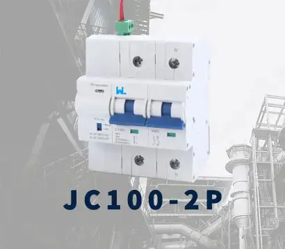 JC125-2P
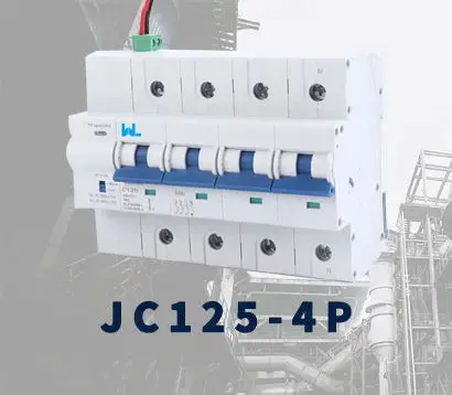 JC125-4P
 JCMX
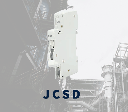 JCSD
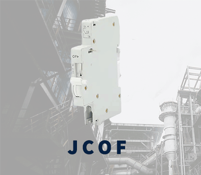 JCOF
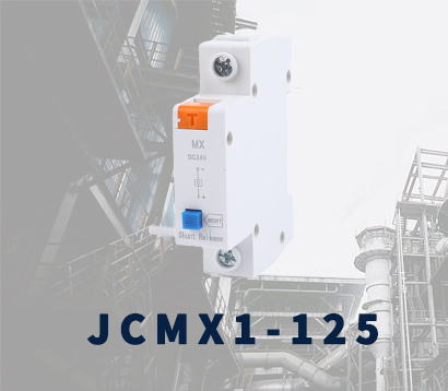 JCMX1-125
 JCOF1-125
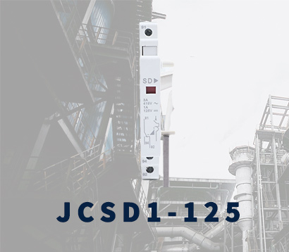 JCSD1-125
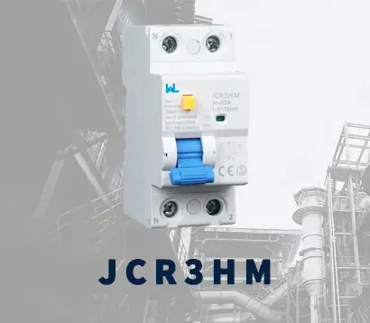 JCR3HM
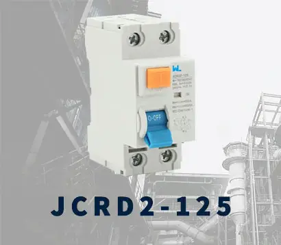 JCRD2-125
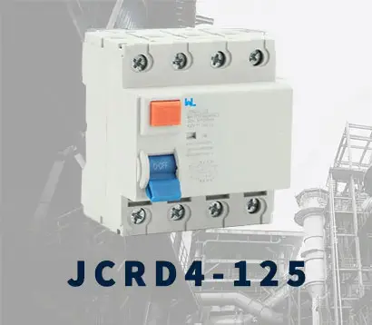 JCRD4-125
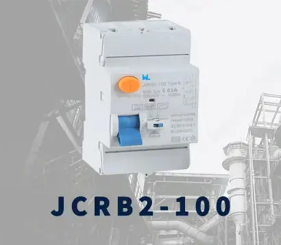 JCRB2-100
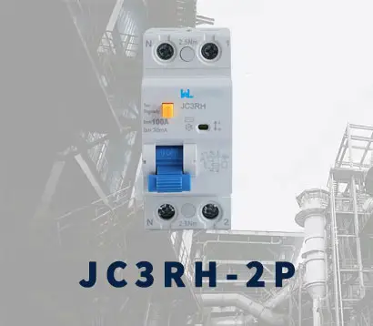 JC3RH-2P
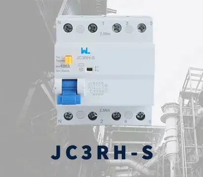 JC3RH-S
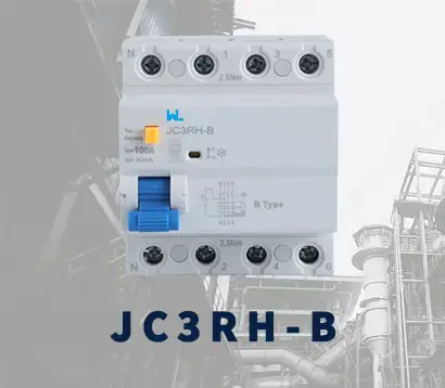 JC3RH-B
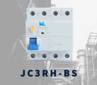 JC3RH-BS
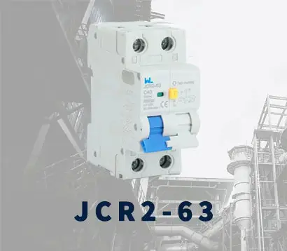 JCR2-63
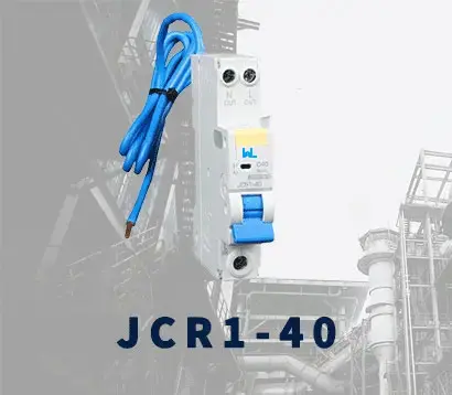 JCR1-40
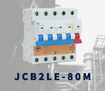 JCB2LE-80M
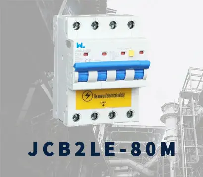 JCB2LE-80M
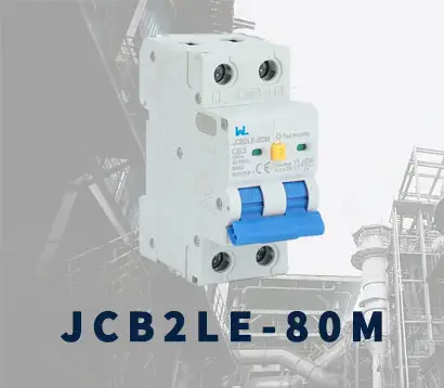 JCB2LE-80M
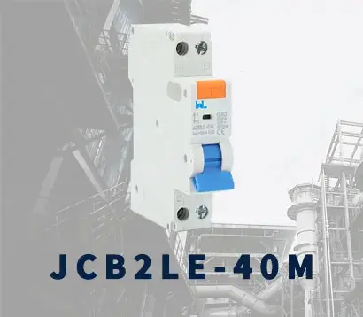 JCB2LE-40M
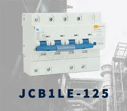 JCB1LE-125
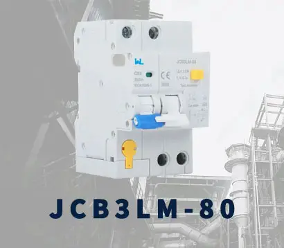 JCB3LM-80
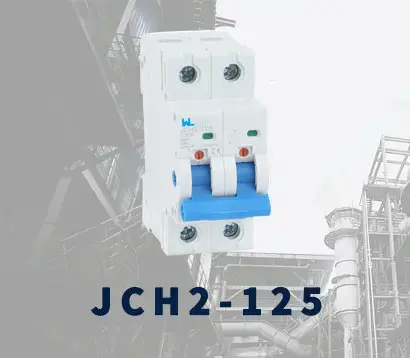 JCH2-125
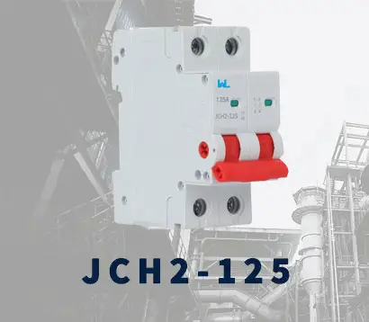 JCH2-125
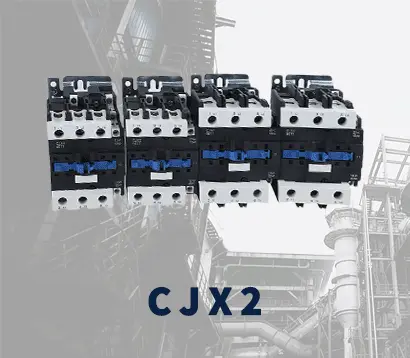 CJX2
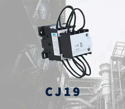 CJ19
 JCMCU
 JCHA
 JCSD-40
 JCSD-60
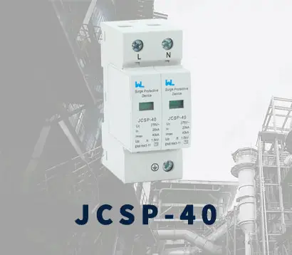 JCSP-40
 JCSP-60
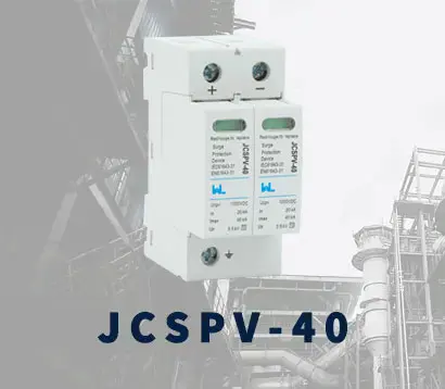 JCSPV
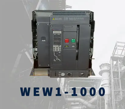 WEW1-1000
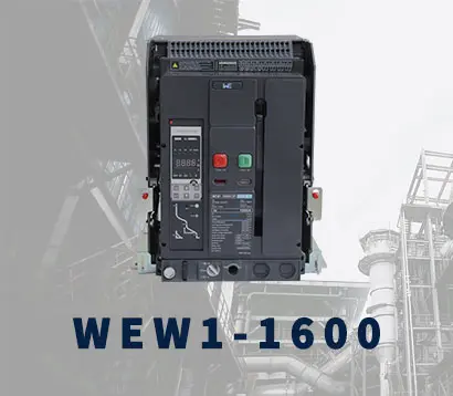 WEW1-1600
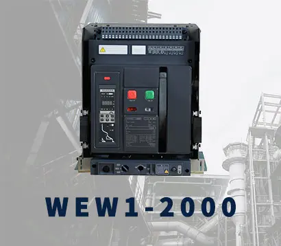 WEW1-2000
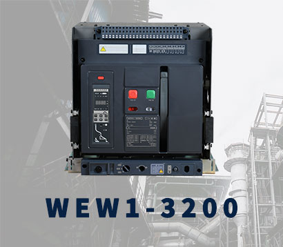 WEW1-3200
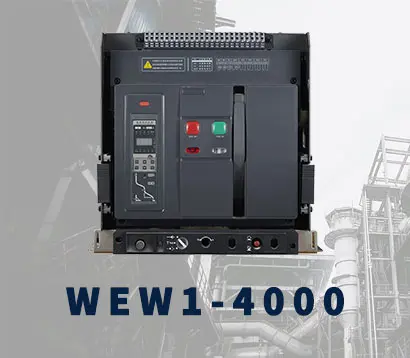 WEW1-4000
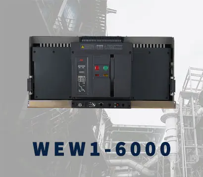 WEW1-6300
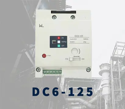 DC6-125
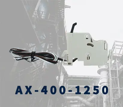 AX-400-1250
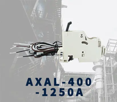 AXAL-400-1250A
 AL-400-1250
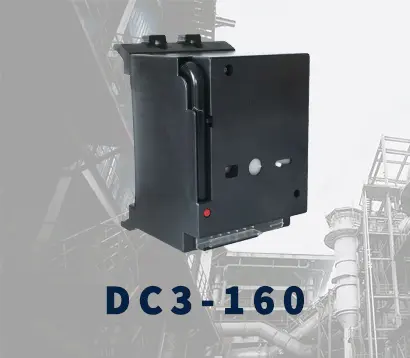 DC3-160
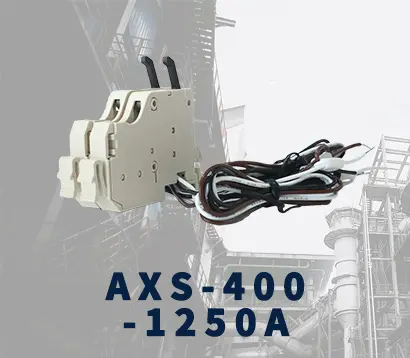 AXS-400-1250A
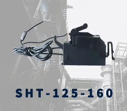 SHT-125-160
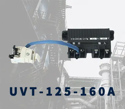 UVT-125-160A
 P-250A-3P-A
 400-3P/4P terminal cover
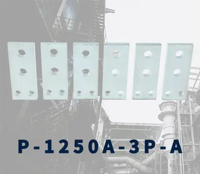 1250-3Pmccb accessories busbar
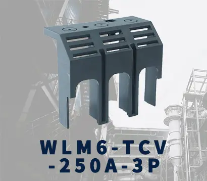 250-3P terminal conver
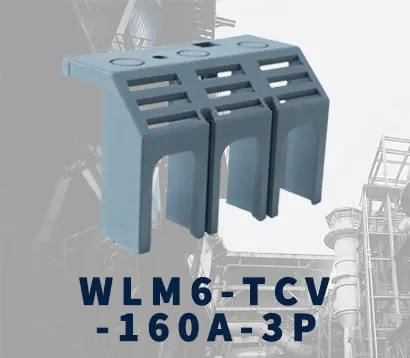 WLM6-TCV-160A-3P
 WLM6-MIP-250A
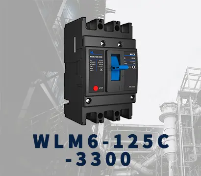 WLM6-125A-3300 3P/4P
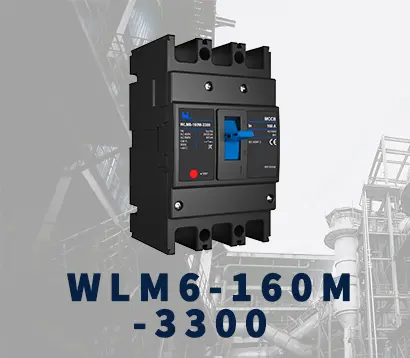 WLM6-160A-3300 3P/4P
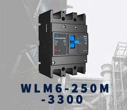 WLM6-250A-3300 3P/4P
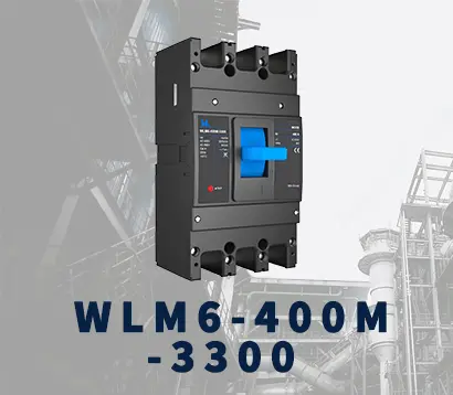 WLM6-400A-3300 3P/4P
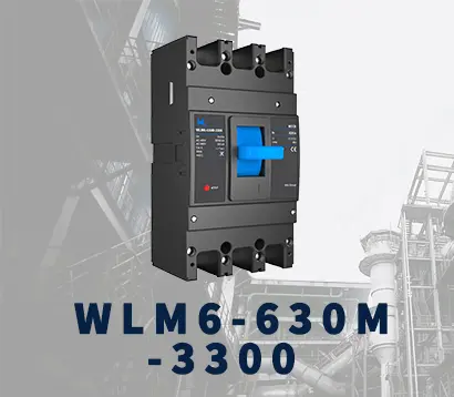 WLM6-630A-3300 3P/4P
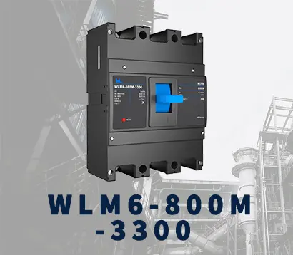 WLM6-800A-3300 3P/4P
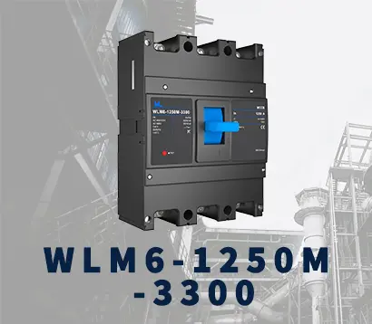 WLM6-1250A-3300 3P/4P
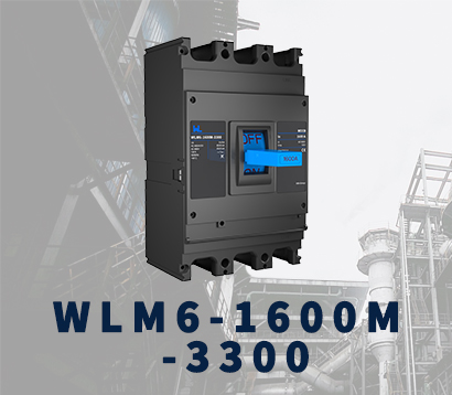 WLM6-1600A-3300 3P/4P
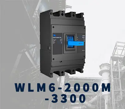 WLM6-2000A 3P/4P
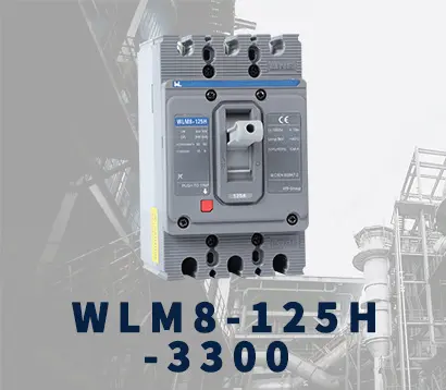 WLM8-125H-3300
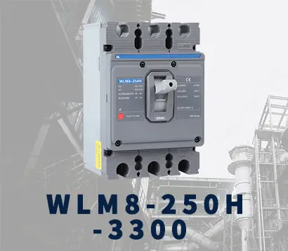 WLM8-250H-3300
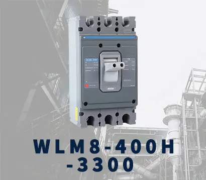 WLM8-400H-3300
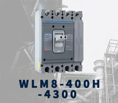 WLM8-400H-4300
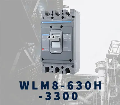 WLM8-630H-3300
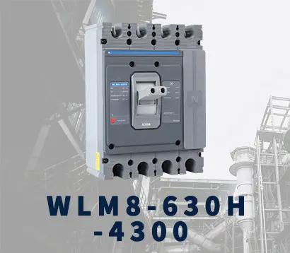 WLM8-630H-4300
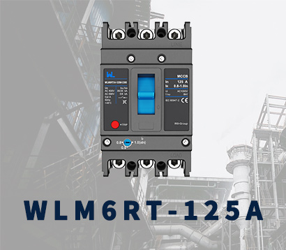 WLM6RT-125A
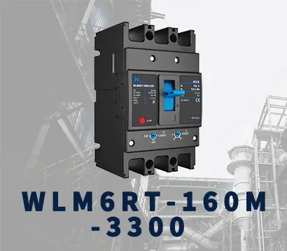 WLM6RT-160A
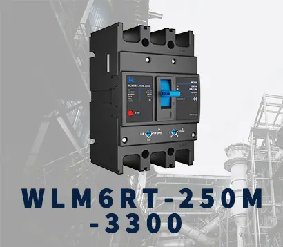 WLM6RT-250A
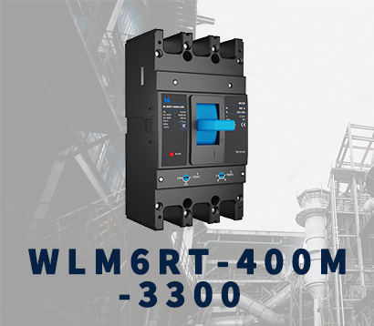 WLM6RT-400A
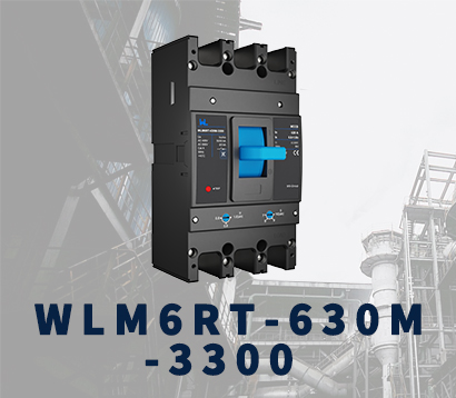 WLM6RT-630A
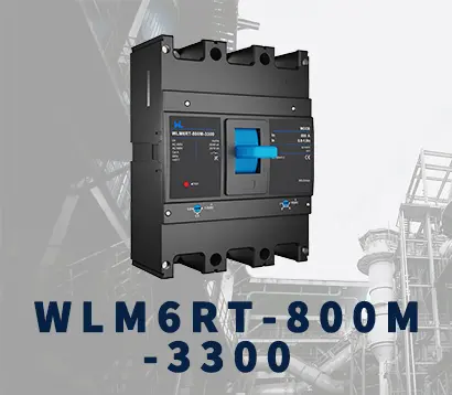 WLM6RT-800A
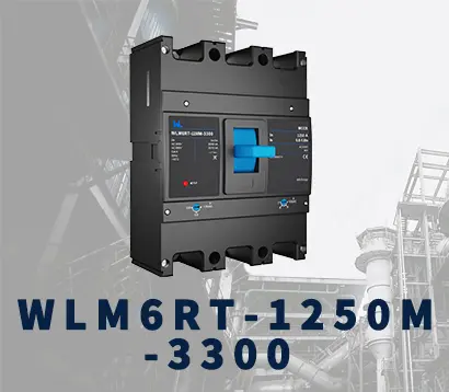 WLM6RT-1250A
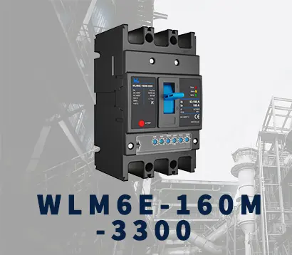 WLM6E-160A-3300 3P
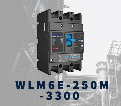 WLM6E-250A-3300
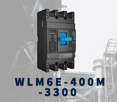 WLM6E-400A-3300 3P/4P
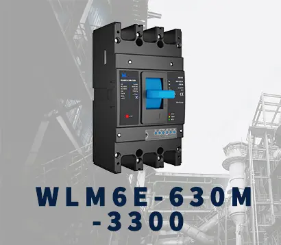 WLM6E-630A-3300
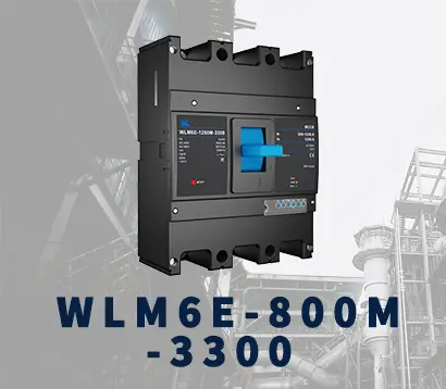 WLM6E-800A-3300 3P/4P
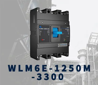 WLM6E-1250A-3300
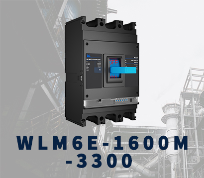 WLM6E-1600-3300 3P/4P
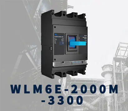 WLM6E-2000A-3300 3P/4P
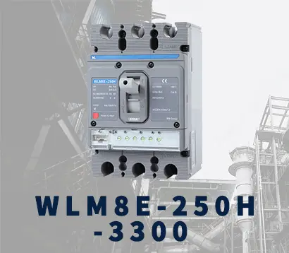 WLM8E-250H-3300
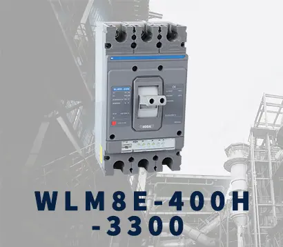 WLM8E-400H-3300
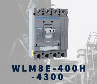 WLM8E-400H-4300
 WLM8E-630H-3300
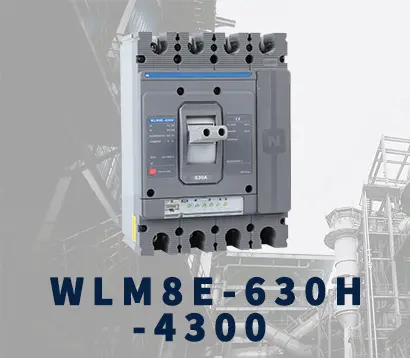 WLM8E-630H-4300
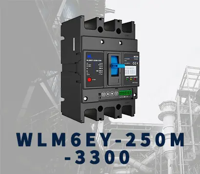 WLM6EY-250-3300 3P/4P
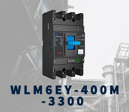 WLM6EY-400 3P/4P
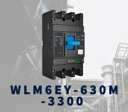 WLM6EY-630 3P/4P
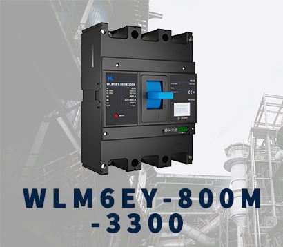 WLM6EY-800A 3P/4P
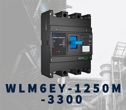 WLM6EY-1250A 3P/4P
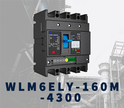 WLM6ELY-160A
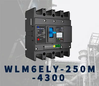 WLM6ELY-250A
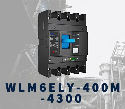 WLM6ELY-400A
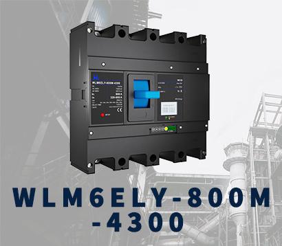 WLM6ELY-800A
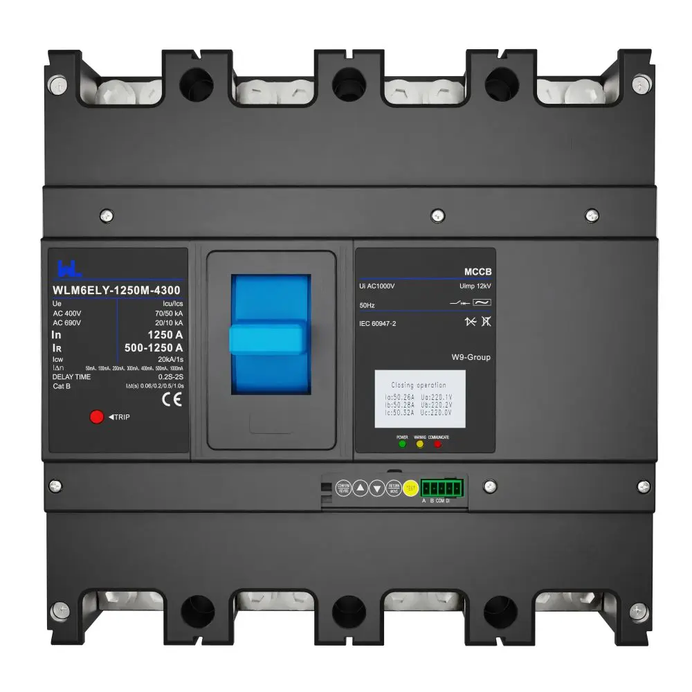 WLM6ELY-1250A
 WLM8EY-250H-3300
 WLM8EY-400H-3300
 WLM8EY-630H-3300
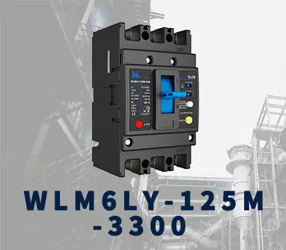 WLM6LY-125A
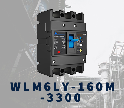 WLM6L-160A
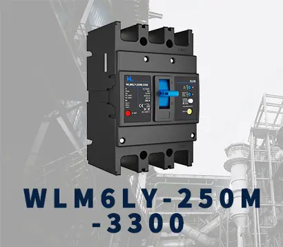 WLM6LY-250A
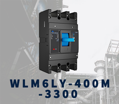 WLM6LY-400A
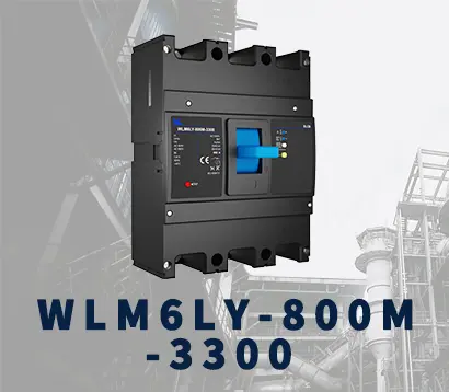 WLM6LY-800A
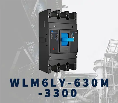 WLM6LY-630A
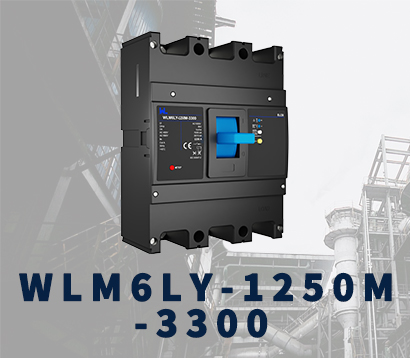 WLM6LY-1250A
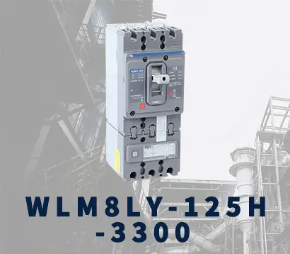 WLM8LY-125H-3300
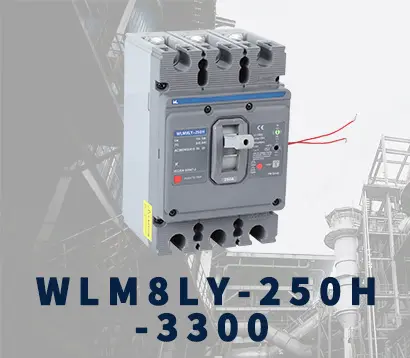 WLM8LY-250H-3300
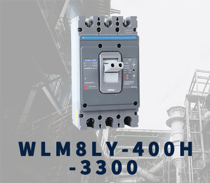 WLM8LY-400H-3300
 WLM8LY-630H-3300
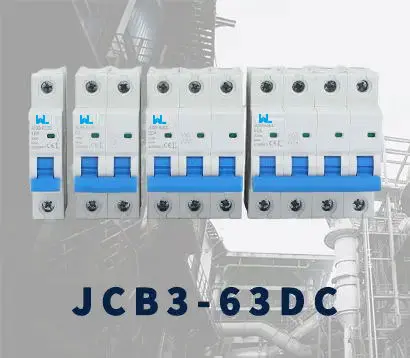 JCB3-63DC
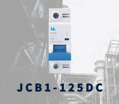 JCB1-125DC
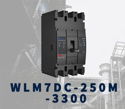 WLM7DC-250A-2300 2P/3P
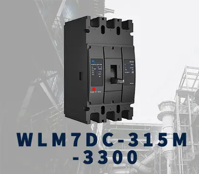 WLM7DC-315A-3300 2P/3P
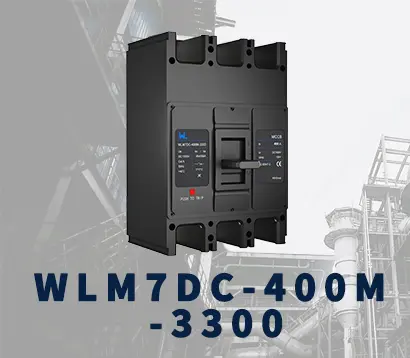 WLM7DC-400A-2300 2P/3P
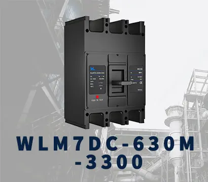 WLM7DC-630A-3300 3P
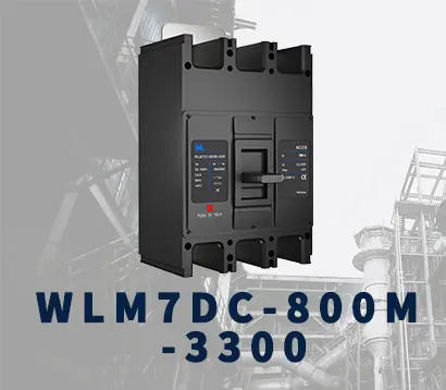 WLM7DC-800A-2300 2P/3P
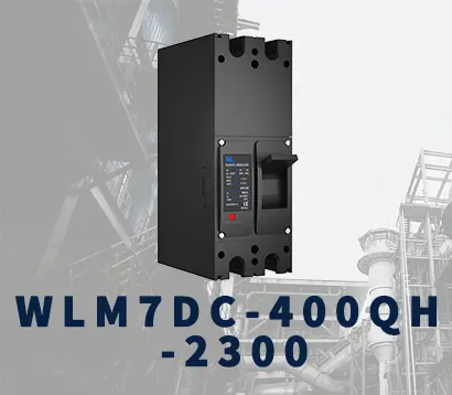 WLM7DC-400A 2300
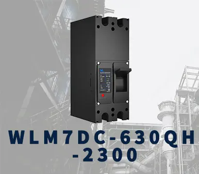 WLM7DC-630A-2300 2P
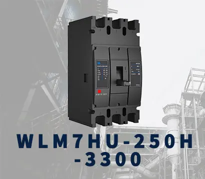 WLM7HU-250-3300 3P
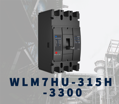 WLM7HU-315-3300 3P
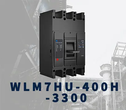 WLM7HU-400-3300 3P
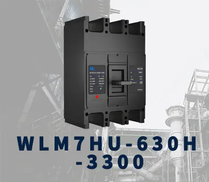 WLM7HU-630-3300 3P
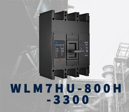 WLM7HU-800-3300 3P
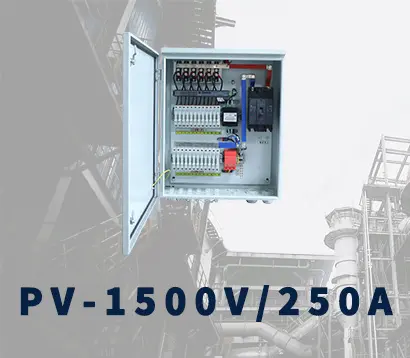 PV-1500V/250A
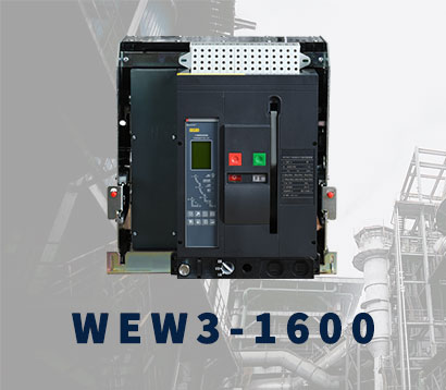 WEW3-1600
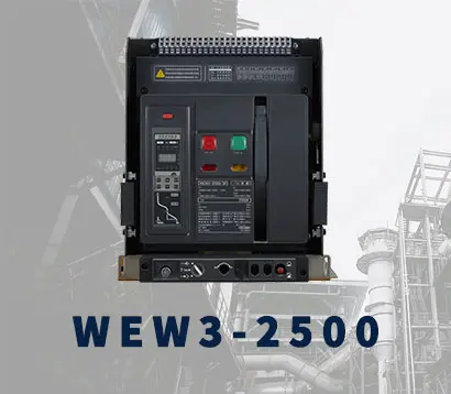 WEW3-2500
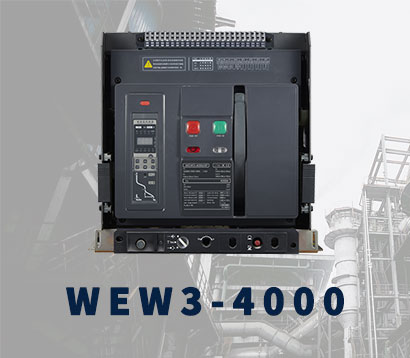 WEW3-4000
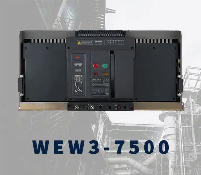 WEW3-7500






7 Tips to Choose the Right MCCB Molded Case Circuit Breaker
Selecting the right Molded Case Circuit Breaker Mccb is not a box-ticking exercise. It is a field decision that affects equipment, people, and business continuity. A breaker may fit the panel and still be wrong for the installation. Its rated current, breaking capacity, trip curve, insulation voltage, and coordination requirements must match the actual system. Cable size matters too. So does the motor’s starting current.
Mike Holt, a respected electrical-training author, states a practical principle: “The overcurrent device must protect the conductor, not merely the load.” That idea gives this guide its direction. The seven tips will examine load calculations, short-circuit levels, adjustable trip settings, pole configurations, environmental conditions, accessories, and compliance with manufacturer instructions. These details become real in a plant room: warm terminals, limited enclosure space, dust, vibration, and a motor that starts several times each hour.
Experience also teaches humility. A catalogue rating does not guarantee a correct installation. Field measurements may reveal unexpected harmonics, future expansion, or a fault level higher than the original design assumed. Sometimes, the simplest choice is not the safest choice. Engineers should verify data with approved documentation and involve a qualified professional when conditions are uncertain. This article offers a practical framework, not a substitute for design verification. Used carefully, these seven tips can help readers compare MCCBs with greater confidence and avoid expensive protection mistakes.

Define Load Requirements: Rated Current, Voltage, Poles, and Duty Cycle
Choosing an MCCB starts with a measured load profile, not a catalog current. Record normal current, starting current, voltage, phases, and operating hours. The IEA Electricity 2024 report projects global electricity demand will rise by about 4% annually through 2026. That growth makes accurate capacity planning more important in expanding facilities. For continuous loads, many installations apply a 125% sizing rule under NEC requirements, subject to local code. Do not treat this as a blanket breaker rating. Conductor ampacity, ambient temperature, and enclosure conditions also matter. A 100 A load may need a 125 A frame, but coordination checks must confirm it.
Match voltage to the system and verify the MCCB’s insulation and utilization ratings. Select two poles for single-phase line-to-line circuits, or three poles for three-phase circuits. Neutral switching depends on the design. Pole count is not decorative. It changes isolation and fault behavior. Check available short-circuit current at the installation point. IEC 60947-2 requires short-circuit performance to suit declared system conditions. Duty cycle also matters. Motors can draw five to seven times running current during starting, although values vary. Frequent starts create heat, and an MCCB is not a contactor. One field mistake is sizing from nameplate current alone. I still question that shortcut when loads cycle sharply.
| Tip | Load Requirement to Define | Example Load Data | Calculation or Selection Basis | Recommended MCCB Configuration | Why It Matters |
|---|---|---|---|---|---|
| 1. Calculate the design current | Rated current and expected operating current |
Three-phase resistive heater Load: 30 kW Voltage: 400 V AC |
Current = P ÷ (√3 × V × power factor) 30,000 ÷ (1.732 × 400 × 1.0) ≈ 43.3 A |
Select an MCCB with a rated current of approximately 50 A, subject to cable ampacity and local code requirements. | The breaker rating should be high enough for normal operation but low enough to protect the conductors from overload. |
| 2. Allow for continuous loading | Duty cycle and duration of operation |
Continuous HVAC load: 32 A Operating time: 3 hours or more |
Where the applicable installation rules require a 125% continuous-load factor: 32 A × 1.25 = 40 A minimum circuit rating |
A 40 A or 50 A MCCB may be appropriate after checking conductor ampacity, ambient temperature, enclosure conditions, and the governing electrical code. | Continuous loads can cause long-term thermal stress. The breaker and cable must be selected for sustained current, not only short-term peak current. |
| 3. Match the system voltage | Nominal system voltage and insulation requirements |
Low-voltage distribution system: 400/230 V AC, 50 Hz |
The MCCB voltage rating must be equal to or greater than the highest applicable system voltage. For a 400 V system, a common suitable class is 415 V AC or higher, when permitted by the installation design. | Use a breaker with an AC voltage rating suitable for the system, such as 415 V AC for a 400 V three-phase network. | An incorrectly rated breaker may not safely interrupt or insulate the circuit during normal operation or a fault. |
| 4. Select the correct number of poles | Phase arrangement and neutral switching requirements |
Three-phase motor circuit with no switched neutral Supply: 3-phase, 400 V AC |
Three live phases require three protected poles. A neutral pole is added only when the design requires simultaneous neutral isolation or protection according to local rules. | Use a 3-pole MCCB for the three-phase motor circuit. Use a 4-pole MCCB where neutral switching is required. | Pole selection ensures that all required conductors are disconnected during isolation and that the protection scheme matches the system earthing arrangement. |
| 5. Consider motor starting current | Inrush current, starting method, and trip characteristic |
Three-phase motor: Running current: 28 A Direct-on-line starting current: commonly about 5–8 times rated current |
Possible starting current range: 28 A × 5 to 8 = approximately 140–224 A |
Select an adjustable thermal-magnetic or electronic-trip MCCB with an instantaneous or short-time setting that avoids nuisance tripping while still protecting the motor circuit and conductors. | A breaker sized only for running current may trip during normal starting. Coordination with the motor starter, overload relay, and cable is essential. |
| 6. Check the short-circuit interrupting rating | Prospective short-circuit current and interrupting capacity |
Calculated prospective fault current at the installation point: 18 kA RMS |
The MCCB interrupting capacity at the applicable voltage must be at least the prospective fault current. A practical design margin may be selected where required by the project specification. | Choose an MCCB with an interrupting rating of at least 18 kA at the system voltage; a 25 kA rating may provide additional margin if available and suitable. | The interrupting rating confirms that the breaker can safely clear a fault without unacceptable damage or rupture. |
| 7. Verify coordination and environmental conditions | Ambient temperature, enclosure, selectivity, and available adjustment range |
Installation environment: 45°C ambient Upstream breaker: 160 A Downstream MCCB: 63 A |
Confirm temperature derating, terminal capacity, enclosure heat dissipation, cable correction factors, and time-current coordination with upstream and downstream protective devices. | A 63 A adjustable-trip MCCB may be suitable only after verifying its derated current, trip settings, breaking capacity, and coordination study. | Correct coordination reduces unnecessary outages and helps ensure that the device nearest to the fault operates first. |
Related Posts
-
How to Choose the Right Electric MCCB for Global Buyers?
-
Exploring the Future of Thermal Magnetic MCCB at the 138th China Import and Export Fair in 2025
-
Exploring Future Trends in After Sales Support and Repair Costs for Best Molded Case Breakers
-
How to Choose the Best Thermal Magnetic MCCB for Your Needs?
-

Ultimate Guide to Understanding Molded Case Breakers for Your Electrical Needs
-
Top Tips for Using Square D MCCB Effectively?