How to Choose the Right Electric MCCB for Global Buyers?
Choosing the right Electric MCCB is not a simple catalog exercise. Global buyers must match protection performance with real operating conditions. A breaker installed in a dusty factory faces different risks from one used in a clean commercial building. Voltage, current, fault level, ambient temperature, enclosure space, and coordination all matter.
Electrical protection specialist Daniel K. Mensah explains, “A reliable MCCB is chosen from the fault conditions first, not from the price tag.” This principle should guide every purchasing decision. Buyers need to check the rated operational voltage, continuous current, short-circuit breaking capacity, pole configuration, and trip-unit options. A 250A frame does not always provide 250A of usable protection. Temperature derating can change the result.
Look closely at regional requirements. Certification markings, test reports, installation methods, and documentation may differ between markets. A product suitable for one distribution board may not satisfy another project’s inspection process. Ask suppliers for current datasheets, routine test evidence, wiring diagrams, and traceable quality records. That small step prevents expensive confusion later.
The selection process is not perfect. Real sites often contain incomplete load data, uncertain future expansion, or poorly documented cable routes. Buyers should acknowledge these gaps instead of hiding them. Independent verification can expose weak assumptions before shipment. This guide will examine technical ratings, safety coordination, environmental durability, supplier credibility, and lifecycle cost. The goal is practical confidence, not the cheapest Electric MCCB on paper.
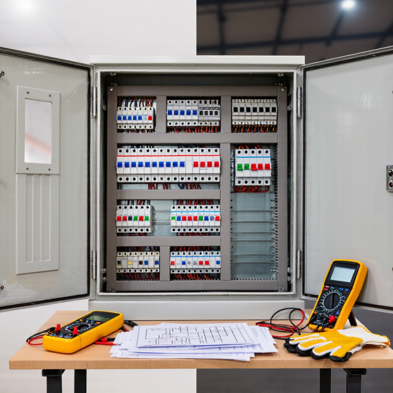
Define MCCB Ratings: IEC 60947-2, 690 V AC, and 10–630 A Frames
Global buyers should treat an MCCB nameplate as a technical contract, not a catalogue shortcut.
IEC 60947-2 defines requirements for low-voltage circuit-breakers, including testing, isolation, and short-circuit performance.
At 690 V AC, verify the rated operational voltage, frequency, number of poles, and insulation coordination.
A 10–630 A frame range does not mean every frame suits every installation.
Select the continuous current rating after checking conductor size, ambient temperature, enclosure ventilation, and installation altitude.
The IEA’s Electricity 2024 report forecasts global electricity demand to grow by about 4% annually through 2026.
That growth increases pressure on compact distribution panels and dependable fault protection.
Confirm Icu against the prospective short-circuit current at the installation point.
Check Ics separately, because it reflects tested performance after interruption.
A useful field lesson is easy to miss.
A 630 A frame may need derating.
The trip setting may also be lower than the frame rating.
For motor loads, consider starting current and coordination with upstream protection.
For photovoltaic or battery systems, examine bidirectional current and DC requirements; a 690 V AC MCCB is not automatically suitable for DC.
IEC 60947-2 offers the framework, but local installation rules still affect the final choice.
The specification can still be wrong.
Recheck every value against the actual panel drawings, fault study, and test documentation.
Match Breaking Capacity: Compare Icu and Ics from 10 kA to 100 kA
Selecting an electric MCCB starts with the available short-circuit current at the installation point. A 10 kA fault level suits some small commercial panels, but industrial feeders may require 50 kA or 100 kA. Confirm the value with a fault study, not a rough estimate.
Icu is the ultimate short-circuit breaking capacity. It shows the highest prospective fault current the MCCB can interrupt under specified test conditions. Ics is the service short-circuit capacity. It indicates whether the breaker can interrupt a fault and remain suitable for continued operation. For example, an MCCB rated at 50 kA Icu and 25 kA Ics offers less operational resilience than one with 50 kA for both ratings. Check the rating at your actual system voltage.
The numbers need context. A breaker may show 100 kA at 240 V, but a lower value at 415 V. Read the manufacturer’s test table carefully. Compare Icu and Ics under IEC 60947-2 conditions, then match them with the panel’s busbar strength and coordination study. In practical panel reviews, buyers sometimes choose Icu alone and overlook Ics. That decision can increase downtime after a major fault. It is an easy mistake. I would also verify ambient temperature, cable length, and upstream protection, because real installations rarely match laboratory conditions exactly.
How to Choose the Right Electric MCCB for Global Buyers? - Match Breaking Capacity: Compare Icu and Ics from 10 kA to 100 kA
Reference comparison for low-voltage AC MCCBs tested according to IEC 60947-2. Icu is the ultimate short-circuit breaking capacity; Ics is the service short-circuit breaking capacity.
Reference Icu
(kA rms) |
Typical Application Range |
Possible Ics Test Levels as a Percentage of Icu |
Selection Check |
Ics = 25% Icu
(kA rms) |
Ics = 50% Icu
(kA rms) |
Ics = 75% Icu
(kA rms) |
Ics = 100% Icu
(kA rms) |
| 10 |
Small commercial loads and final distribution |
2.50 |
5.00 |
7.50 |
10.00 |
Use only where the calculated prospective fault current is below the verified Icu at the specified voltage. |
| 15 |
Commercial panels and light industrial feeders |
3.75 |
7.50 |
11.25 |
15.00 |
Confirm the manufacturer’s tested Ics value; do not assume Ics equals 100% of Icu. |
| 25 |
General industrial distribution and motor feeders |
6.25 |
12.50 |
18.75 |
25.00 |
Suitable only when the available fault current and system voltage remain within the published rating. |
| 36 |
Industrial switchboards and transformer secondary panels |
9.00 |
18.00 |
27.00 |
36.00 |
Often selected for higher fault levels; verify short-circuit coordination with upstream devices. |
| 50 |
High-capacity industrial distribution |
12.50 |
25.00 |
37.50 |
50.00 |
Check the rating at the actual Ue, frequency, altitude, enclosure, and connection configuration. |
| 65 |
Large industrial plants and utility-fed assemblies |
16.25 |
32.50 |
48.75 |
65.00 |
Consider a higher Ics when continuity of service and post-fault re-energization are important. |
| 70 |
High-fault-level main distribution boards |
17.50 |
35.00 |
52.50 |
70.00 |
Verify the assembly short-circuit withstand rating and the complete selective-coordination study. |
| 100 |
Very high fault-level industrial or infrastructure systems |
25.00 |
50.00 |
75.00 |
100.00 |
Use only with documented test data at the required voltage and installation conditions. |
Important: The Ics columns are calculated reference values based on common IEC 60947-2 Ics percentages of Icu. They are not universal product ratings. The actual Ics, Icu, Ue, pole configuration, and test conditions must be confirmed from the specific MCCB technical documentation.
Key Selection Dimensions for Global Buyers
| Selection Dimension |
What to Verify Before Ordering |
| Prospective short-circuit current |
Obtain the calculated or measured prospective fault current at the installation point. Select an Icu that is equal to or greater than this value at the actual operating voltage. |
| Icu versus Ics |
Icu indicates the maximum fault current the MCCB can interrupt under the specified test conditions. Ics indicates the service breaking capacity and is more relevant when the device may need to remain serviceable after a fault. |
| Rated operational voltage (Ue) |
Breaking-capacity values can vary with voltage. Confirm the rating at the intended network voltage, such as 230 V, 400 V, 415 V, 480 V, or another declared value. |
| Frequency and network type |
Check AC frequency, single-phase or three-phase operation, neutral requirements, and whether the application is AC, DC, or mixed service. |
| Poles and neutral protection |
Choose the required number of poles and determine whether the neutral pole must be switched, protected, or have a reduced rating. |
| Coordination and selectivity |
Verify time-current curves, let-through energy, cascading or backup protection, and selective coordination with upstream and downstream protective devices. |
| Installation conditions |
Check ambient temperature, altitude, enclosure size, ventilation, conductor arrangement, terminal type, and any required derating. |
| Compliance documentation |
Request the applicable standard declaration, test reports or certificates, dimension drawings, wiring diagrams, operating instructions, and routine-test information. |
Verify Poles, Voltage, and Frequency for 2-, 3-, and 4-Pole Systems
Choosing an electric MCCB for global use starts with three facts: poles, voltage, and frequency. I have seen a 3-pole breaker ordered for a four-wire load. The enclosure fitted, but neutral switching requirements did not. For a 2-pole system, confirm whether both live conductors need simultaneous disconnection. This matters in single-phase circuits with line-to-line or line-to-neutral supplies.
A 3-pole MCCB suits many three-phase loads, including motors and distribution feeders. Check voltage between phases, not only the phase-to-neutral value. A 4-pole model adds a switched neutral and may improve isolation in specific systems. It is not automatically safer. The neutral arrangement, earthing method, and local installation rules must support it. Ask for rated operational voltage, insulation voltage, and short-circuit breaking capacity. These figures must match the site, not merely the purchase request. Frequency also deserves attention. Most equipment uses 50 or 60 Hz, but compatibility still requires verification. Trip behavior may change with application conditions.
Before approval, compare the MCCB data plate with electrical drawings and utility information. Record pole count, phase configuration, voltage, frequency, neutral practice, and prospective fault current. An overlooked detail can invalidate a correct-looking selection. I have also seen buyers assume a 4-pole device solves every neutral problem. That assumption needs questioning. A qualified engineer should review coordination, cable capacity, ambient temperature, and enclosure conditions. Specifications can be incomplete. Request written clarification when any datasheet value remains unclear.
Check Derating, Certification, and Environmental Limits Above 40°C
How to Choose the Right Electric MCCB for Global Buyers?
Derating becomes critical when the surrounding temperature exceeds 40°C. An MCCB rated at 100 A may not safely carry 100 A inside a hot enclosure. Check the manufacturer’s derating curve, not only the front-label rating. Measure the enclosure temperature near the breaker terminals. Heat from adjacent devices can raise it further. A practical selection should match the reduced current, cable capacity, and expected load profile. Leave a sensible margin. Small margins often disappear in real installations.
Certification also requires careful verification. For many markets, IEC 60947-2 is an important reference for MCCB performance. Buyers should confirm the exact model, pole configuration, voltage, frequency, and interrupting ratings. Check both Icu and Ics values. A certificate for a similar product is not enough. Request current test reports and confirm whether approval covers the intended country. Local requirements may add testing or marking obligations. Paperwork can look convincing.
Environmental limits deserve equal attention. Review operation above 40°C, storage temperature, humidity, pollution level, altitude, and salt exposure. Installations above 2,000 meters may require additional derating because of reduced air density. Condensation can affect terminals and trip mechanisms. Dust can restrict heat dissipation. I have seen designs rely on laboratory conditions, then struggle inside sealed metal cabinets. That assumption needs reconsideration. A site survey, thermal check, and documented verification provide stronger evidence than a catalogue number alone.
How to Choose the Right Electric MCCB for Global Buyers?
Check Derating, Certification, and Environmental Limits Above 40°C
The chart shows a representative planning profile for an MCCB rated at 100% current at 40°C ambient temperature.
Above 40°C, the usable continuous current commonly needs to be reduced, but the exact derating curve is product-specific and must be confirmed in the manufacturer’s datasheet.
Global buyers should also verify IEC 60947-2 or UL 489 certification, installation altitude, humidity, enclosure temperature, and the permitted operating range for the target market.
Example: a 250 A MCCB with an 80% usable-current factor at 60°C should be evaluated at approximately 200 A continuous current before applying any additional installation or grouping corrections.

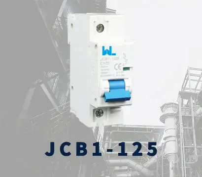 JCB1-125
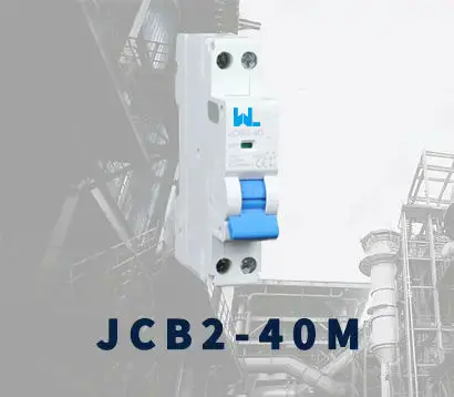 JCB2-40M
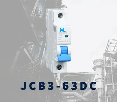 JCB3-63DC
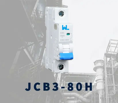 JCB3-80H
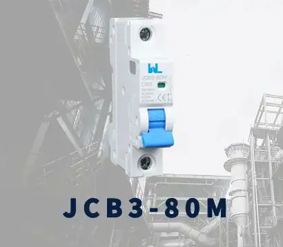 JCB3-80M
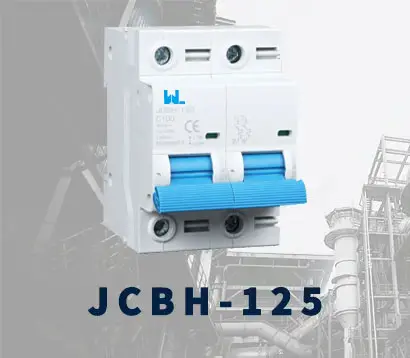 JCBH-125
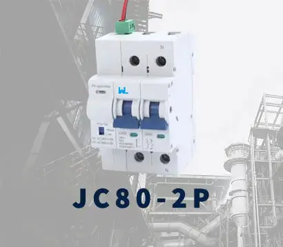 JC80-2P
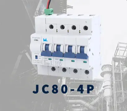 JC80-4P
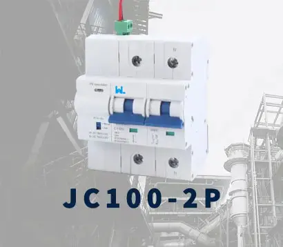 JC125-2P
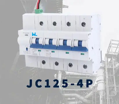 JC125-4P
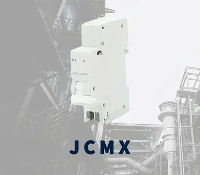 JCMX
JCMX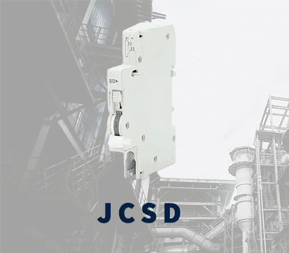 JCSD
JCSD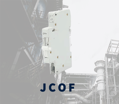 JCOF
JCOF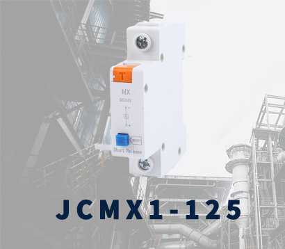 JCMX1-125
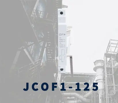 JCOF1-125
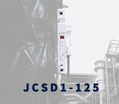 JCSD1-125
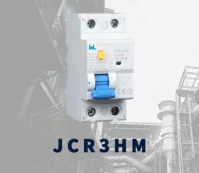 JCR3HM
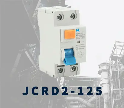 JCRD2-125
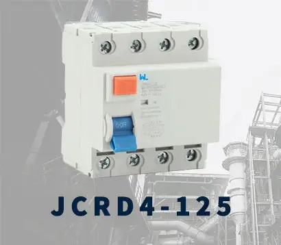 JCRD4-125
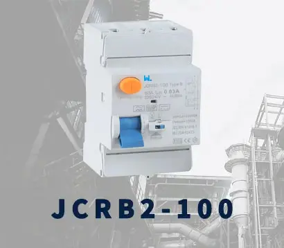 JCRB2-100
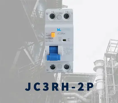 JC3RH-2P
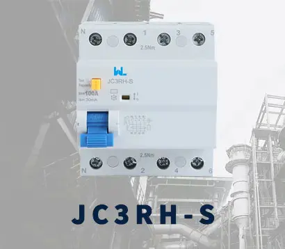 JC3RH-S
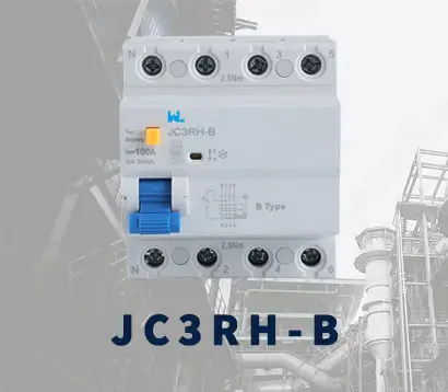 JC3RH-B
 JC3RH-BS
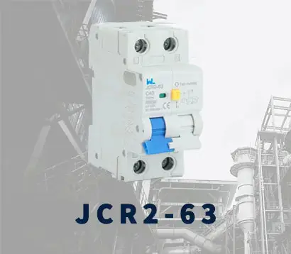 JCR2-63
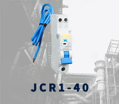 JCR1-40
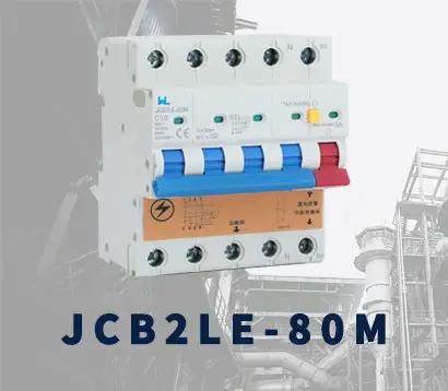 JCB2LE-80M
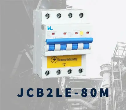 JCB2LE-80M
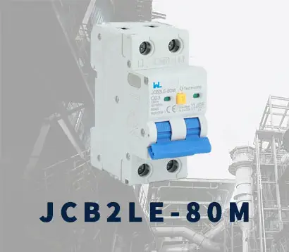 JCB2LE-80M
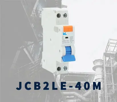 JCB2LE-40M
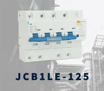 JCB1LE-125
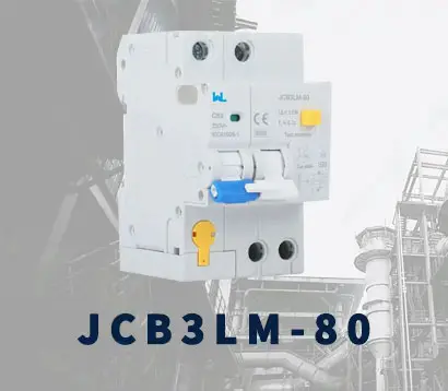 JCB3LM-80
 JCH2-125
 JCH2-125
 CJX2
CJX2 CJ19
CJ19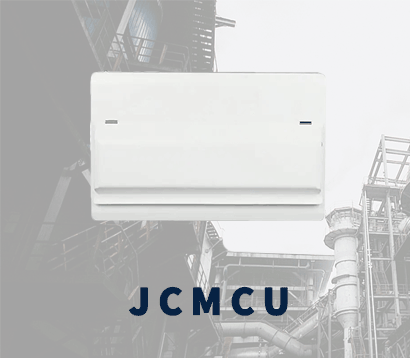 JCMCU
JCMCU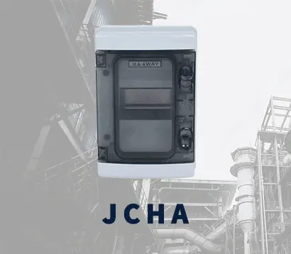 JCHA
JCHA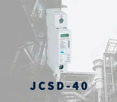 JCSD-40
 JCSD-60
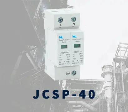 JCSP-40
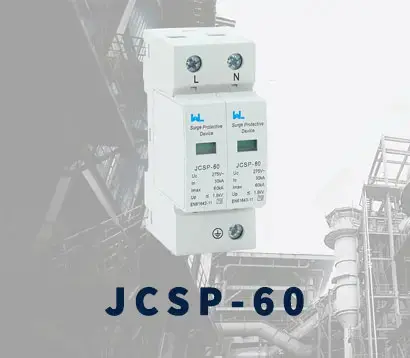 JCSP-60
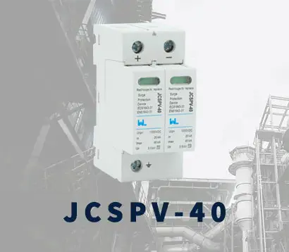 JCSPV
JCSPV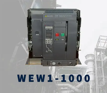 WEW1-1000
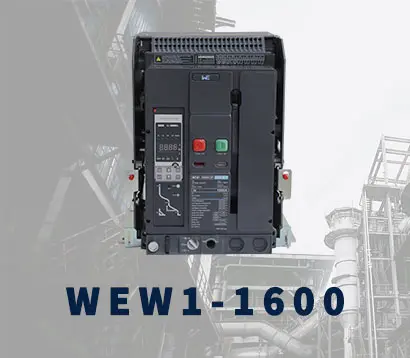 WEW1-1600
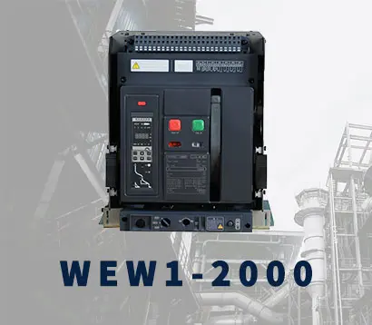 WEW1-2000
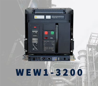 WEW1-3200
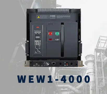 WEW1-4000
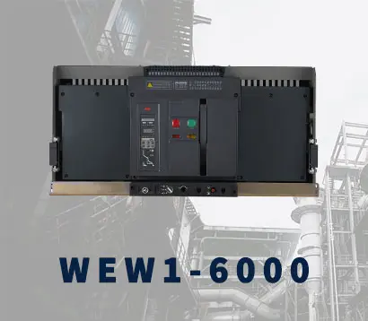 WEW1-6300
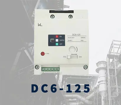 DC6-125
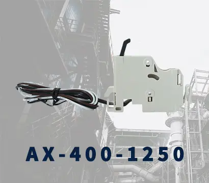 AX-400-1250
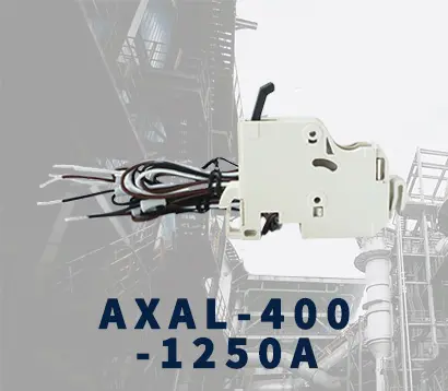 AXAL-400-1250A
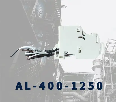 AL-400-1250
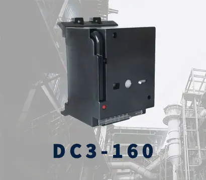 DC3-160
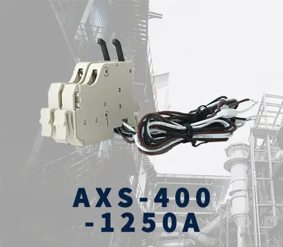 AXS-400-1250A
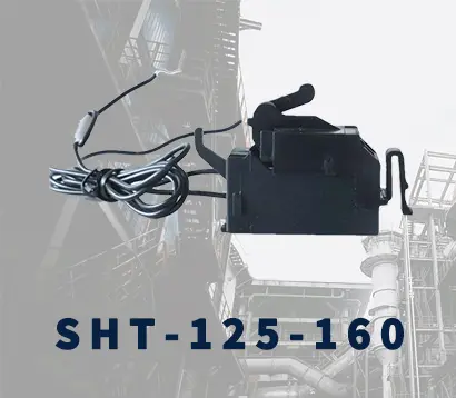 SHT-125-160
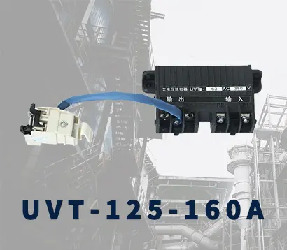 UVT-125-160A
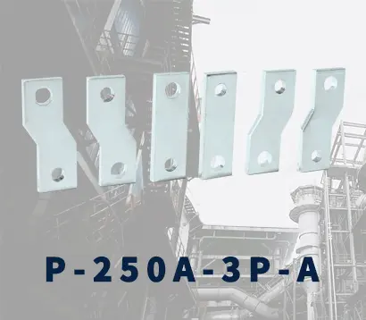 P-250A-3P-A
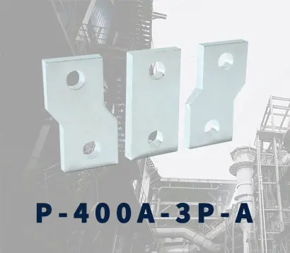 400-3P/4P terminal cover
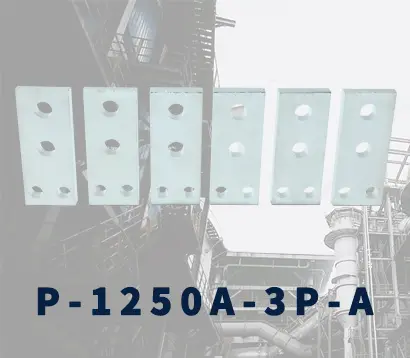 1250-3Pmccb accessories busbar
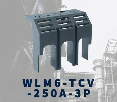 250-3P terminal conver
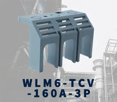 WLM6-TCV-160A-3P
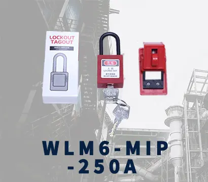 WLM6-MIP-250A
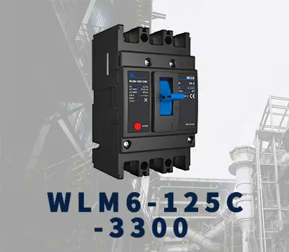 WLM6-125A-3300 3P/4P
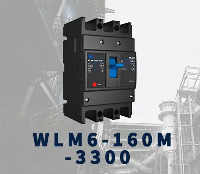 WLM6-160A-3300 3P/4P
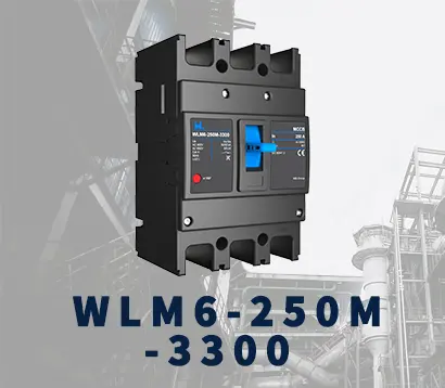 WLM6-250A-3300 3P/4P
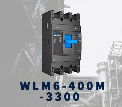 WLM6-400A-3300 3P/4P
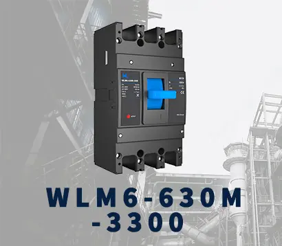 WLM6-630A-3300 3P/4P
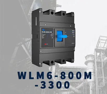 WLM6-800A-3300 3P/4P
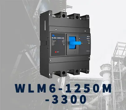 WLM6-1250A-3300 3P/4P
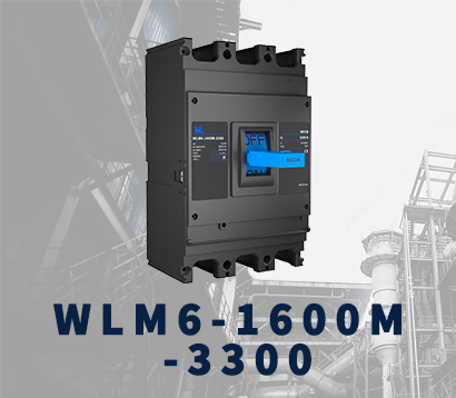 WLM6-1600A-3300 3P/4P
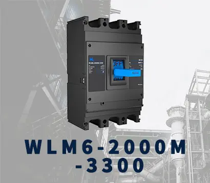 WLM6-2000A 3P/4P
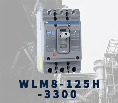 WLM8-125H-3300
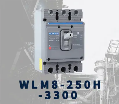 WLM8-250H-3300
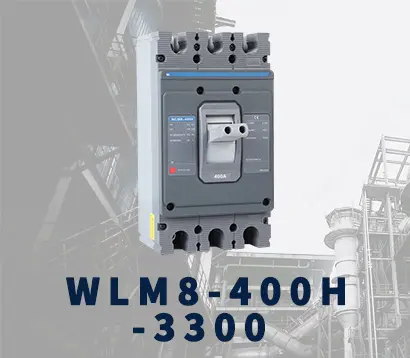 WLM8-400H-3300
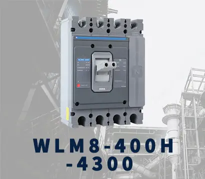 WLM8-400H-4300
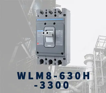 WLM8-630H-3300
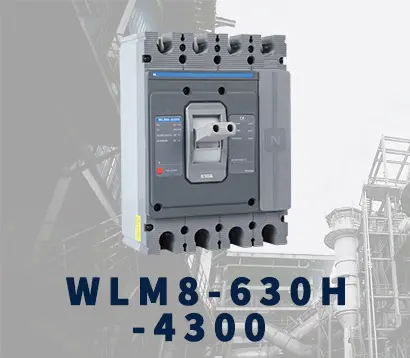 WLM8-630H-4300
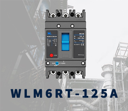 WLM6RT-125A
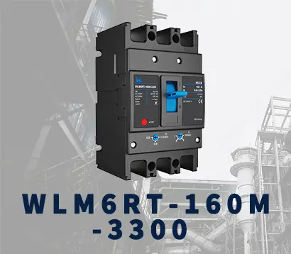 WLM6RT-160A
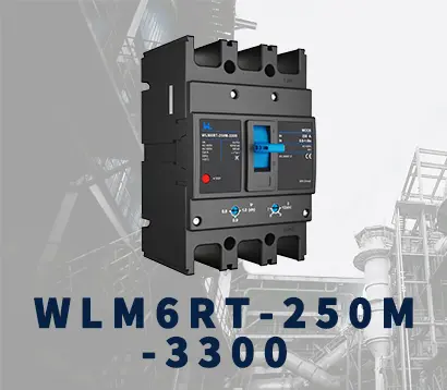 WLM6RT-250A
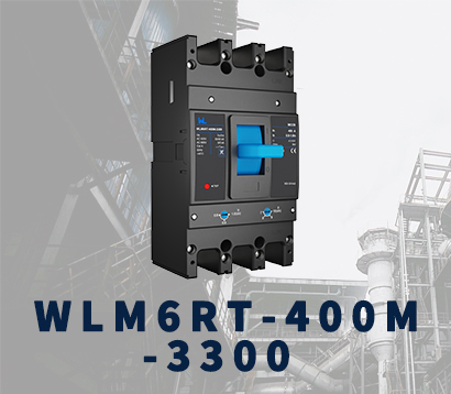 WLM6RT-400A
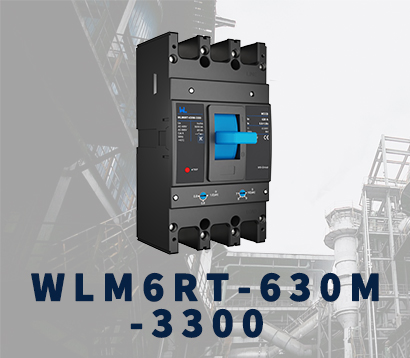 WLM6RT-630A
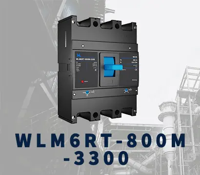 WLM6RT-800A
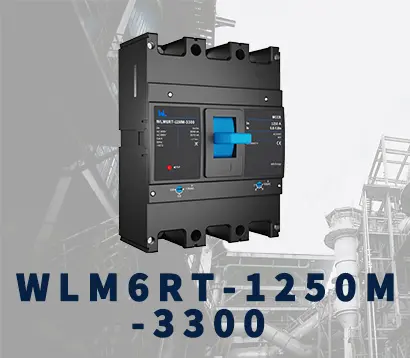 WLM6RT-1250A
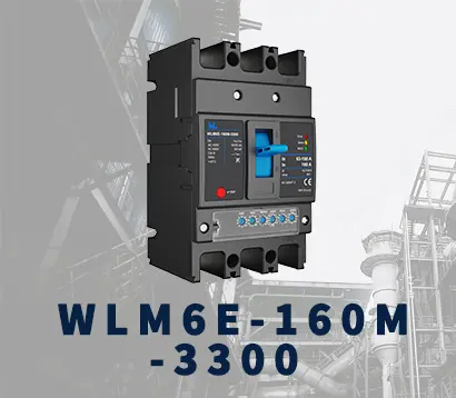 WLM6E-160A-3300 3P
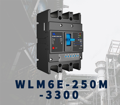 WLM6E-250A-3300
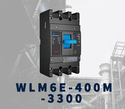 WLM6E-400A-3300 3P/4P
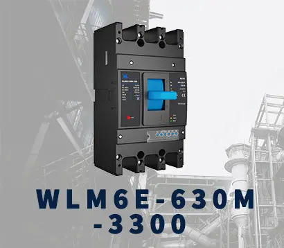 WLM6E-630A-3300
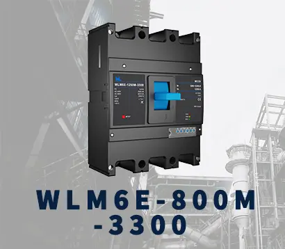 WLM6E-800A-3300 3P/4P
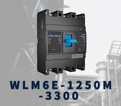 WLM6E-1250A-3300
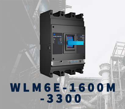 WLM6E-1600-3300 3P/4P
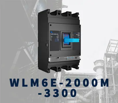 WLM6E-2000A-3300 3P/4P
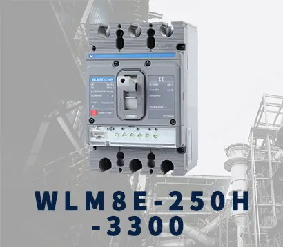 WLM8E-250H-3300
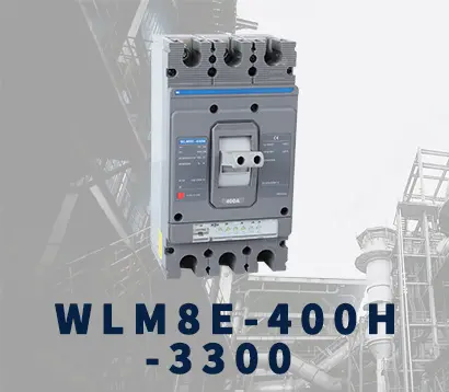 WLM8E-400H-3300
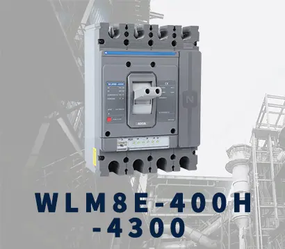 WLM8E-400H-4300
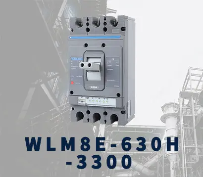 WLM8E-630H-3300
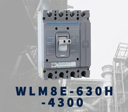 WLM8E-630H-4300
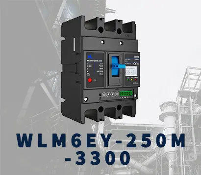 WLM6EY-250-3300 3P/4P
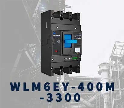 WLM6EY-400 3P/4P
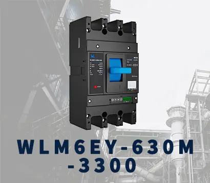 WLM6EY-630 3P/4P
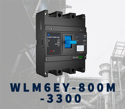 WLM6EY-800A 3P/4P
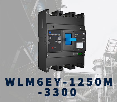 WLM6EY-1250A 3P/4P
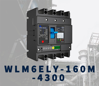 WLM6ELY-160A
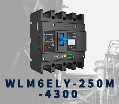 WLM6ELY-250A
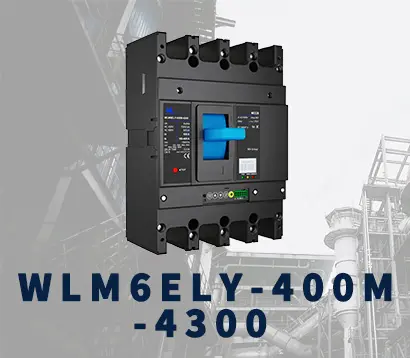 WLM6ELY-400A
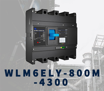 WLM6ELY-800A
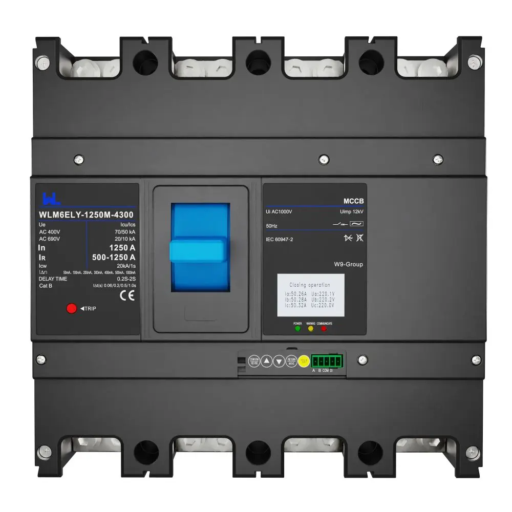 WLM6ELY-1250A
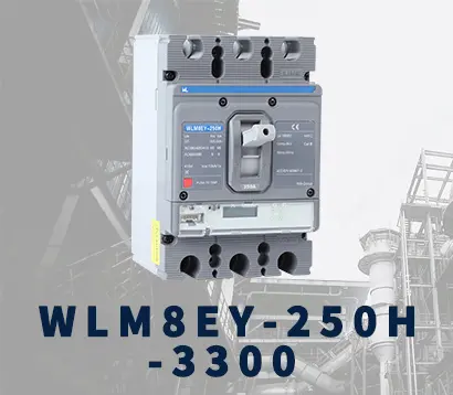 WLM8EY-250H-3300
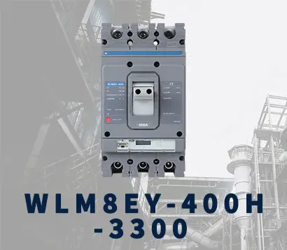 WLM8EY-400H-3300
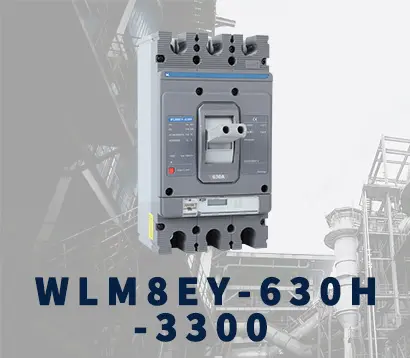 WLM8EY-630H-3300
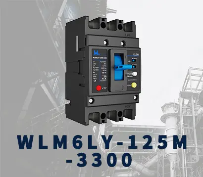 WLM6LY-125A
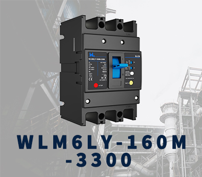 WLM6L-160A
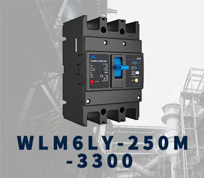 WLM6LY-250A
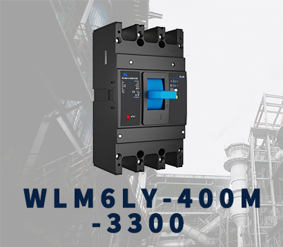 WLM6LY-400A
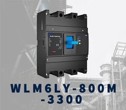 WLM6LY-800A
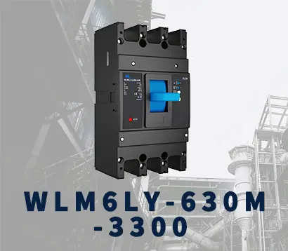 WLM6LY-630A
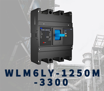 WLM6LY-1250A
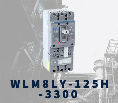 WLM8LY-125H-3300
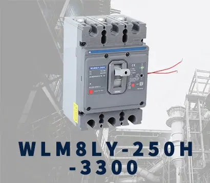 WLM8LY-250H-3300
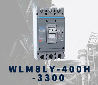 WLM8LY-400H-3300
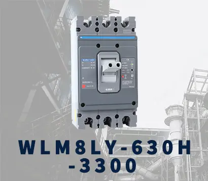 WLM8LY-630H-3300
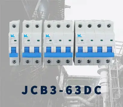 JCB3-63DC
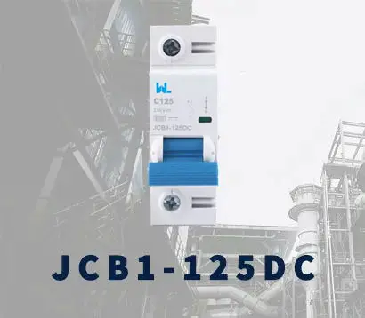 JCB1-125DC
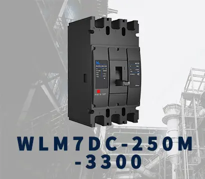 WLM7DC-250A-2300 2P/3P
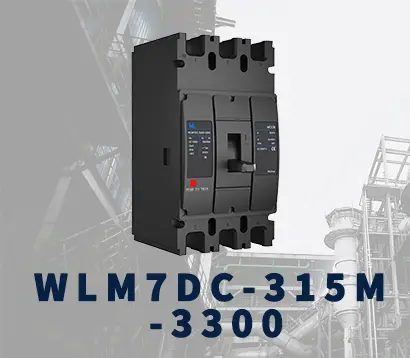 WLM7DC-315A-3300 2P/3P
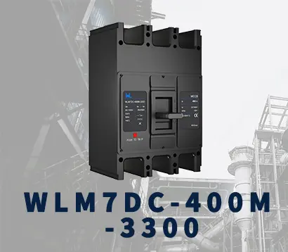 WLM7DC-400A-2300 2P/3P
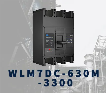 WLM7DC-630A-3300 3P
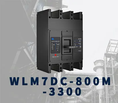 WLM7DC-800A-2300 2P/3P
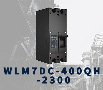 WLM7DC-400A 2300
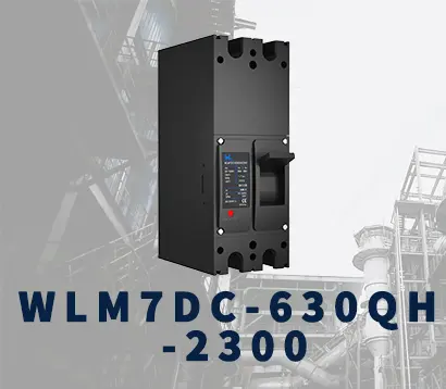 WLM7DC-630A-2300 2P
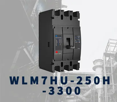 WLM7HU-250-3300 3P
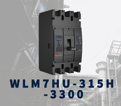 WLM7HU-315-3300 3P
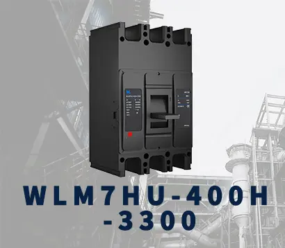 WLM7HU-400-3300 3P
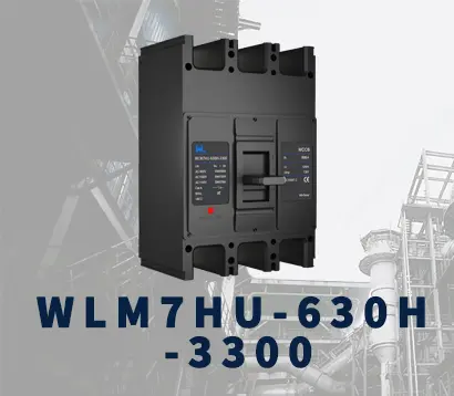 WLM7HU-630-3300 3P
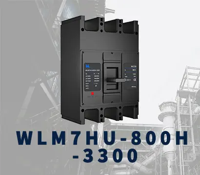 WLM7HU-800-3300 3P
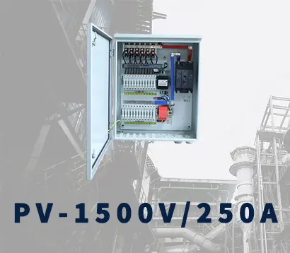 PV-1500V/250A
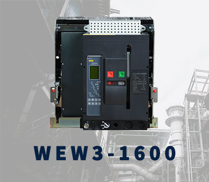 WEW3-1600
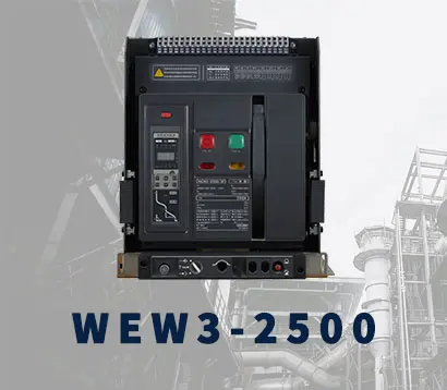 WEW3-2500
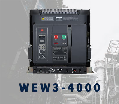 WEW3-4000
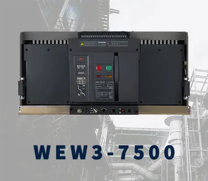 WEW3-7500