| Resistive Heating Loads |
Low inrush current and a relatively stable current profile after energization. |
Thermal-magnetic trip is usually suitable. Electronic trip units may be used where monitoring or adjustable protection is required. |
Typically lower instantaneous sensitivity than motor-starting applications; verify the manufacturer’s adjustment range. |
Short-circuit current at the heater panel or distribution board, plus conductor overload during continuous operation. |
Rated current, continuous-load rating, interrupting capacity, conductor ampacity, and ambient-temperature derating. |
Electric heaters, ovens, hot-water systems, and resistance banks. |
| Induction Motors |
High starting current, commonly several times the motor full-load current, followed by normal running current. |
Adjustable electronic or motor-rated thermal-magnetic protection is preferred to prevent nuisance tripping during acceleration. |
Instantaneous pickup must be high enough to ride through starting current but low enough to clear a close-in fault. Final settings require motor and system data. |
Locked-rotor current, stalled rotor, phase loss, phase-to-phase faults, and available short-circuit current. |
Motor full-load current, starting method, acceleration time, overload relay coordination, cable size, and interrupting rating. |
Pumps, fans, compressors, conveyors, and machine tools. |
| Transformers |
Magnetizing inrush can be several times rated current and may last from cycles to seconds depending on energization conditions. |
Use adjustable short-circuit protection coordinated with transformer inrush and primary-side protection requirements. |
Avoid setting the instantaneous function so low that normal energization causes tripping; use time delay or suitable inrush coordination where available. |
Transformer primary fault, secondary fault reflected to the primary, inrush, and through-fault withstand. |
Transformer kVA, primary and secondary voltage, impedance, inrush profile, available fault current, and protection coordination. |
Distribution transformers, control transformers, and isolation transformers. |
| Capacitor Banks and Power-Factor Correction |
Switching can produce transient current and high-frequency disturbances; capacitor current changes with voltage and frequency. |
Use protection specifically coordinated for capacitor switching and the bank’s continuous current; avoid treating the bank like a purely resistive load. |
Instantaneous settings should tolerate expected switching transients while clearing short-circuit faults rapidly. |
Capacitor terminal faults, switching transients, harmonics, resonance, and failed capacitor units. |
Capacitor rated current, permissible overcurrent, switching duty, harmonic environment, fuse or contactor coordination, and interrupting rating. |
Automatic power-factor correction panels and industrial capacitor banks. |
| Variable-Frequency Drives |
Input current is influenced by rectifiers, DC-link capacitors, harmonics, and drive charging current. |
Use an MCCB approved and coordinated for drive input protection; do not rely on the MCCB alone for motor overload protection. |
Select the instantaneous range to tolerate normal drive charging and operating transients while maintaining short-circuit protection. |
Drive input short circuit, DC-link fault, semiconductor fault, and cable fault between the drive and motor. |
Drive manufacturer’s upstream protection data, input current, short-circuit rating, harmonic current, and line-side coordination. |
Speed-controlled pumps, fans, conveyors, and process machinery. |
| Soft Starters |
Reduced-voltage motor starting lowers starting current compared with direct-on-line starting, but bypass and semiconductor conditions affect protection. |
Use adjustable protection coordinated with the soft starter’s recommended upstream device and motor overload function. |
Set instantaneous protection above the expected starting profile but below the prospective fault current after coordination analysis. |
Semiconductor short circuit, bypass-contactor fault, stalled motor, and downstream cable fault. |
Motor full-load current, start duration, number of starts per hour, bypass arrangement, and manufacturer coordination data. |
Large pumps, compressors, crushers, and high-inertia machines. |
| Lighting and General Socket Circuits |
Usually moderate inrush, but LED drivers, electronic ballasts, and switched-mode power supplies can create brief inrush and harmonic current. |
Thermal-magnetic protection is common; electronic trip units are useful in larger distribution boards with adjustable selectivity. |
Avoid excessive sensitivity to driver inrush while preserving rapid clearing for line-to-line and line-to-ground faults. |
Overloaded final circuits, loose connections, short circuits, and high fault current at socket outlets. |
Design current, cable ampacity, protective-device coordination, earth-fault loop impedance, and interrupting capacity. |
Commercial lighting panels, office distribution, retail areas, and utility outlets. |
| Data-Center and IT Power Distribution |
High availability is required; power supplies may have inrush, nonlinear current, and sensitivity to voltage interruption. |
Adjustable electronic trip units with true RMS sensing and selective coordination are generally appropriate for main and feeder MCCBs. |
Use time-current coordination to prevent upstream tripping for downstream faults; instantaneous protection must still clear high-level faults safely. |
High prospective fault current, bus faults, selective-coordination requirements, and unwanted interruption of critical loads. |
Short-circuit study, arc-flash assessment, selectivity, redundant supply arrangement, maintenance mode, and alarm communications. |
UPS outputs, server distribution, cooling systems, and critical power panels. |
| Welders and Other Intermittent Loads |
Current varies rapidly and may include repeated inrush, low power factor, and duty-cycle changes. |
Use adjustable protection based on the equipment duty cycle and supply characteristics; verify that thermal behavior matches intermittent operation. |
Coordinate with welding current peaks and transformer or inverter input inrush without compromising short-circuit protection. |
Input transformer inrush, repeated overload, cable heating, and fault current at the equipment terminals. |
Rated input current, duty cycle, power factor, supply voltage, cable length, and prospective short-circuit current. |
Arc welders, resistance welders, and fabrication equipment. |
| Long Cable or Remote Subpanels |
Conductor impedance can reduce fault current at the remote end and increase voltage drop. |
Select the MCCB using both overload protection and the minimum fault current at the far end of the circuit. |
Confirm that the instantaneous or short-time function will operate within the required disconnection time at the remote fault level. |
Low-level end-of-line faults, high loop impedance, voltage drop, and conductor thermal damage. |
Cable length, conductor material and size, installation method, loop impedance, fault current range, and disconnection time. |
Warehouse subpanels, outdoor feeders, remote pumps, and building extensions. |
| High Available Short-Circuit Current |
A fault can release substantial thermal and electromagnetic energy in a very short time. |
Choose an MCCB with an interrupting rating equal to or greater than the calculated prospective short-circuit current at the installation point. |
Use instantaneous or short-time settings only after a coordination and arc-flash review; higher settings can increase incident energy. |
Line-to-line, three-phase, line-to-ground faults, and equipment withstand limits. |
Prospective fault current, voltage rating, interrupting capacity, short-time withstand, let-through energy, and enclosure requirements. |
Main switchboards, industrial services, and transformer secondary feeders. |
| Generator-Supplied Loads |
Generator fault current is often lower and decays more quickly than utility fault current; voltage and frequency may also vary during transients. |
Use protection settings that are sensitive enough for the generator fault level while allowing motor starting and generator transient performance. |
Verify the minimum generator short-circuit current and coordinate with generator subtransient reactance, alternator protection, and transfer equipment. |
Low-level faults that may not produce enough current for fast magnetic operation, generator overload, and transient voltage dip. |
Generator rating, subtransient reactance, minimum fault current, neutral grounding, load-step response, and transfer-switch coordination. |
Standby generators, emergency systems, and islanded microgrids. |
| Photovoltaic and Battery Energy Storage Feeders |
Fault contribution depends on inverter controls, battery converters, operating mode, and system topology. |
Use equipment and settings coordinated with the inverter or battery-system protection scheme and applicable installation standard. |
Do not assume utility-style fault current; verify both maximum and minimum fault contributions, including backfeed conditions. |
DC-side faults, AC-side faults, reverse power flow, battery fault current, and isolation during maintenance. |
AC/DC voltage rating, bidirectional current capability, fault contribution, isolation requirements, energy-storage location, and coordination. |
Solar combiner outputs, inverter feeders, battery racks, and energy-storage switchboards. |

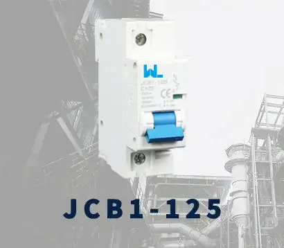 JCB1-125
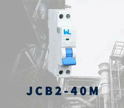 JCB2-40M
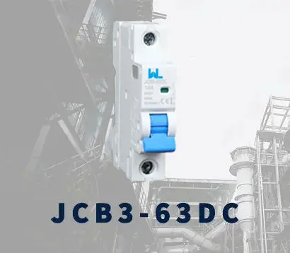 JCB3-63DC
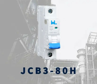 JCB3-80H
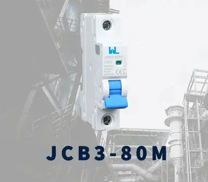 JCB3-80M
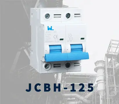 JCBH-125
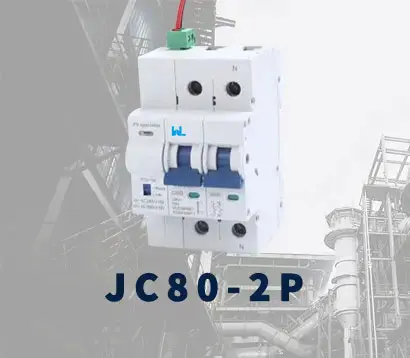 JC80-2P
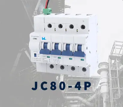 JC80-4P
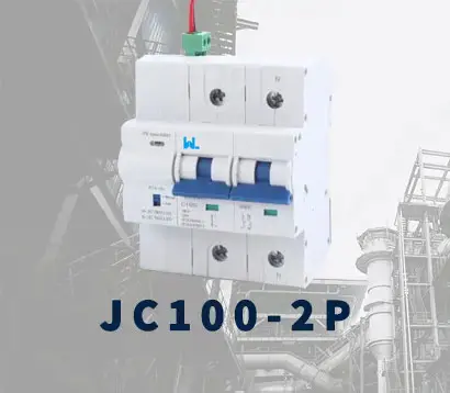 JC125-2P
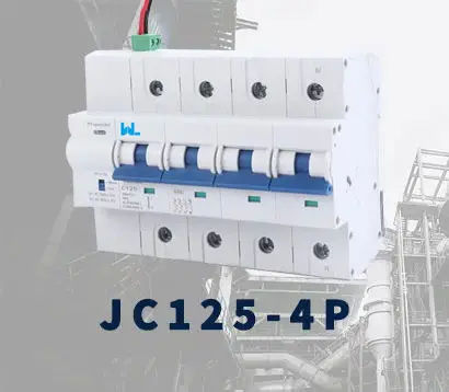 JC125-4P
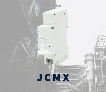 JCMX
JCMX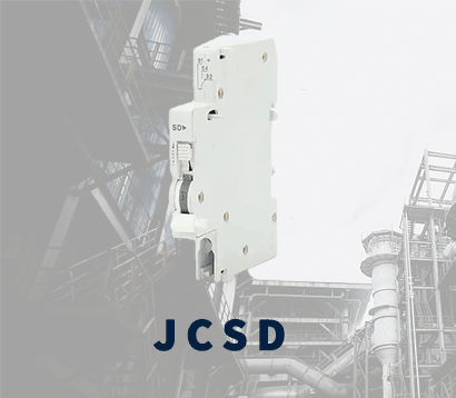 JCSD
JCSD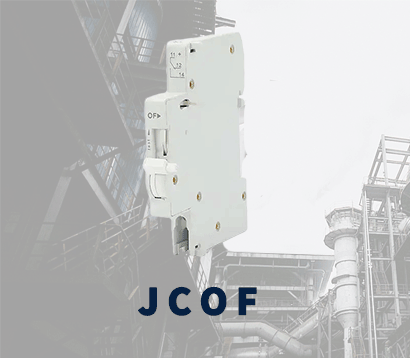 JCOF
JCOF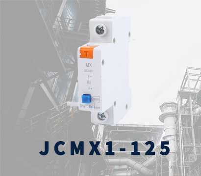 JCMX1-125
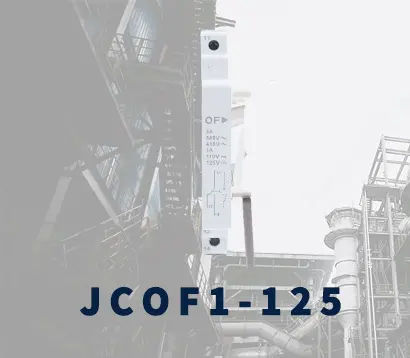 JCOF1-125
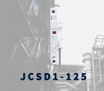 JCSD1-125
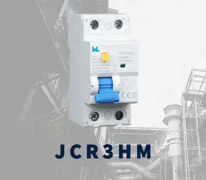 JCR3HM
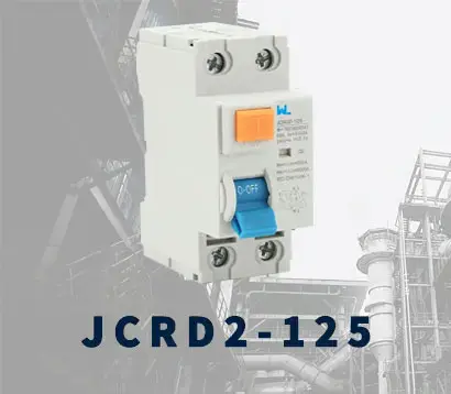 JCRD2-125
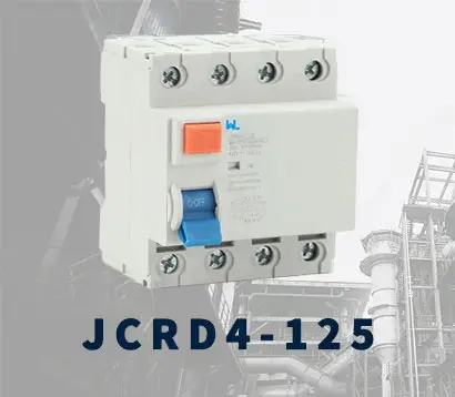 JCRD4-125
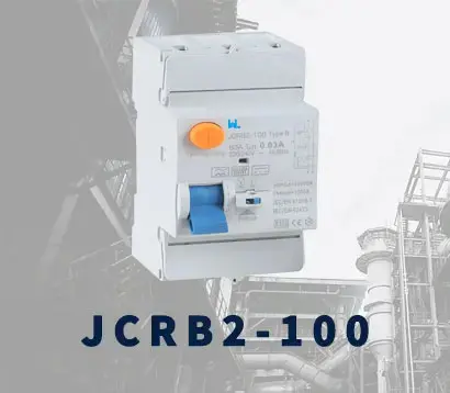 JCRB2-100
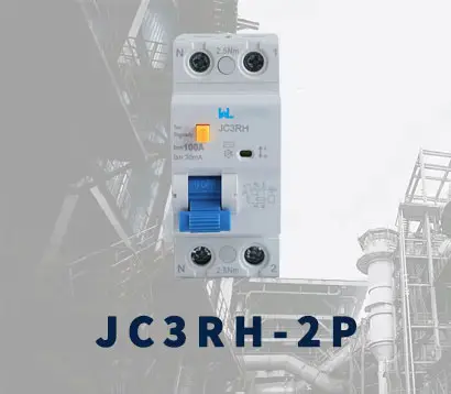 JC3RH-2P
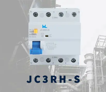 JC3RH-S
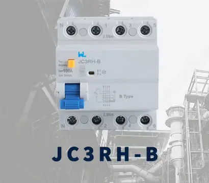 JC3RH-B
 JC3RH-BS
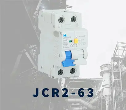 JCR2-63
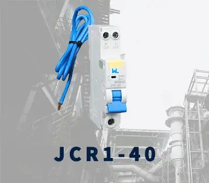 JCR1-40
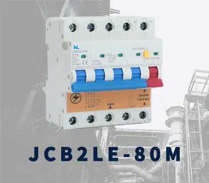 JCB2LE-80M
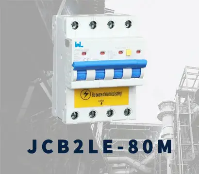 JCB2LE-80M
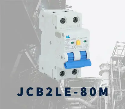 JCB2LE-80M
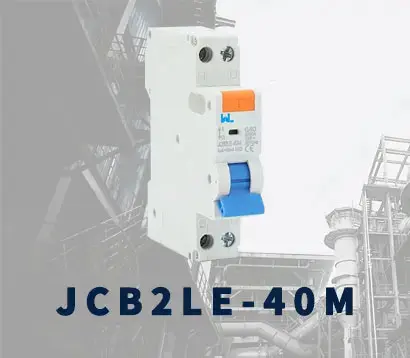 JCB2LE-40M
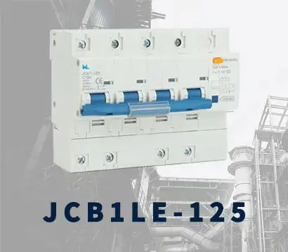 JCB1LE-125
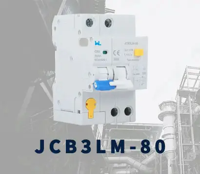 JCB3LM-80
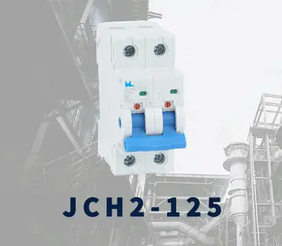 JCH2-125
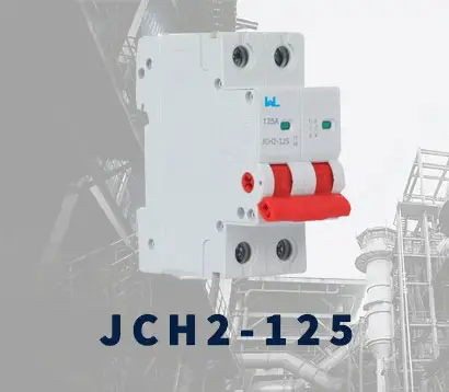 JCH2-125
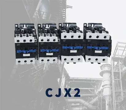 CJX2
CJX2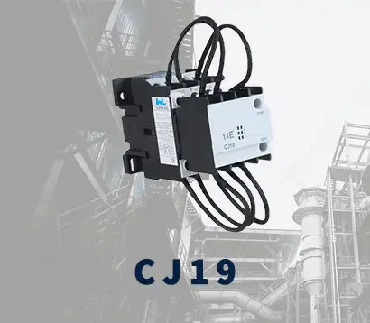 CJ19
CJ19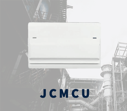 JCMCU
JCMCU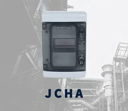 JCHA
JCHA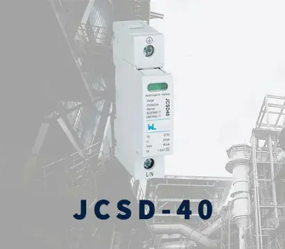 JCSD-40
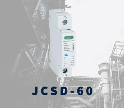 JCSD-60
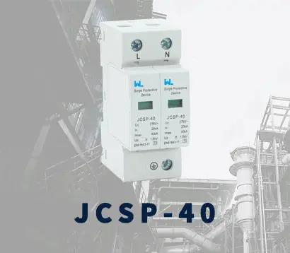 JCSP-40
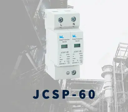 JCSP-60
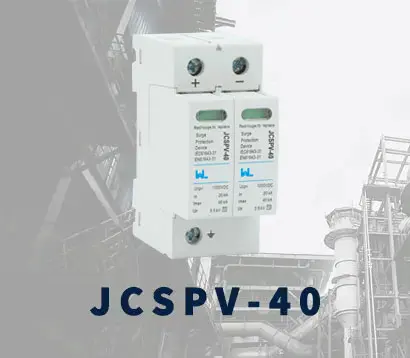 JCSPV
JCSPV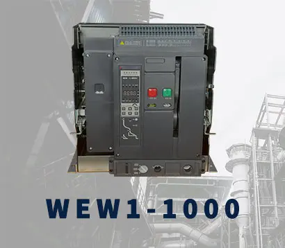 WEW1-1000
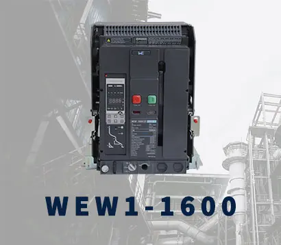 WEW1-1600
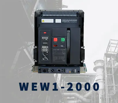 WEW1-2000
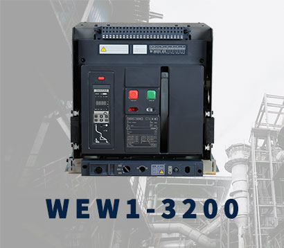 WEW1-3200
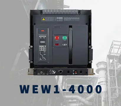 WEW1-4000
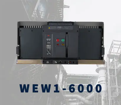 WEW1-6300
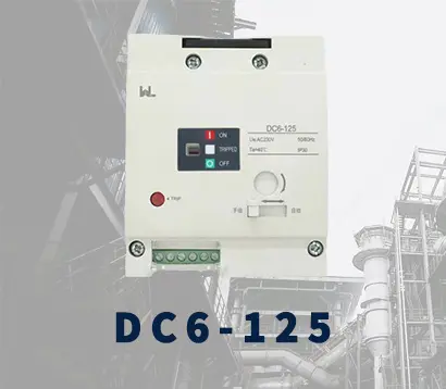 DC6-125
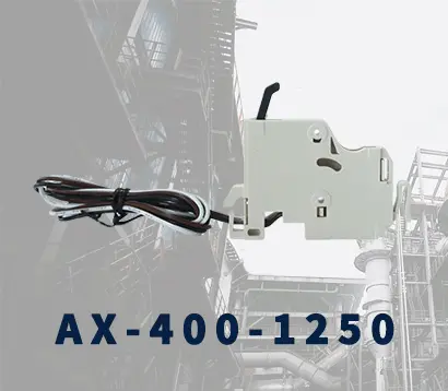 AX-400-1250
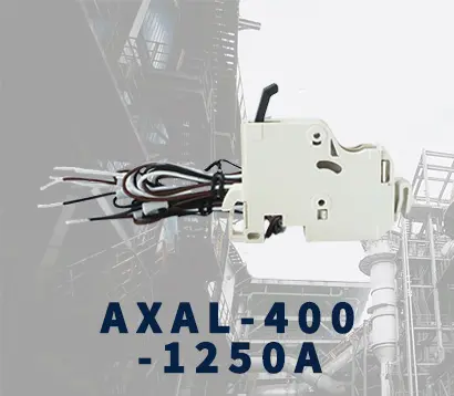 AXAL-400-1250A
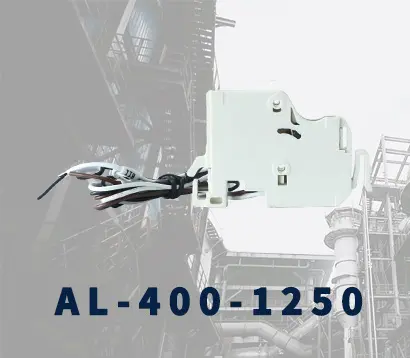 AL-400-1250
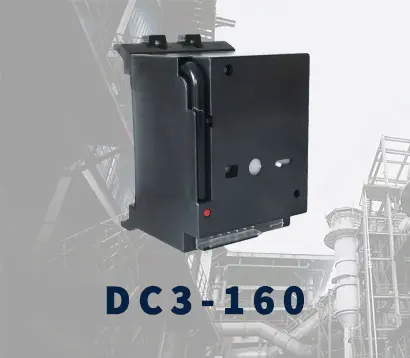 DC3-160
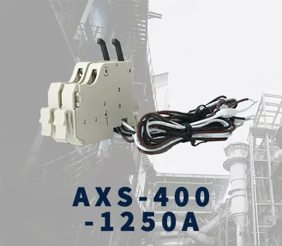 AXS-400-1250A
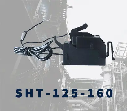 SHT-125-160
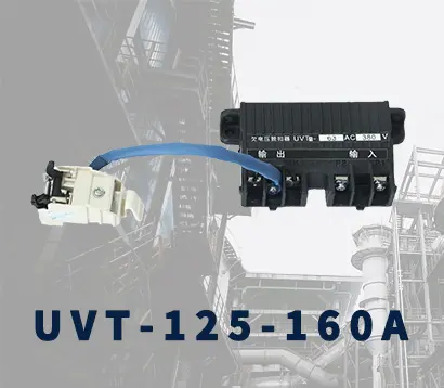 UVT-125-160A
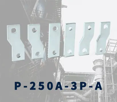 P-250A-3P-A
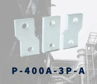 400-3P/4P terminal cover
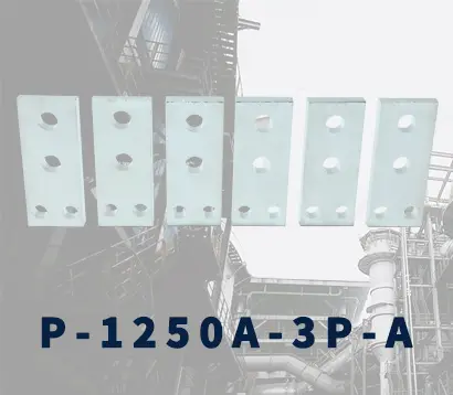 1250-3Pmccb accessories busbar
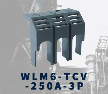 250-3P terminal conver
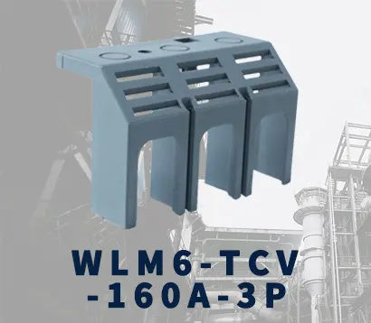 WLM6-TCV-160A-3P
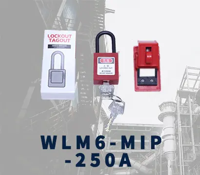 WLM6-MIP-250A
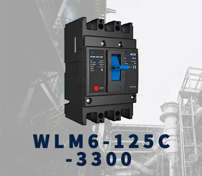 WLM6-125A-3300 3P/4P
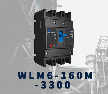 WLM6-160A-3300 3P/4P
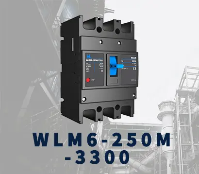 WLM6-250A-3300 3P/4P
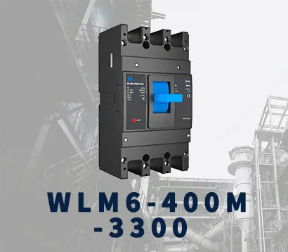 WLM6-400A-3300 3P/4P
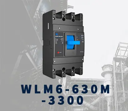 WLM6-630A-3300 3P/4P
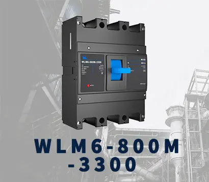 WLM6-800A-3300 3P/4P
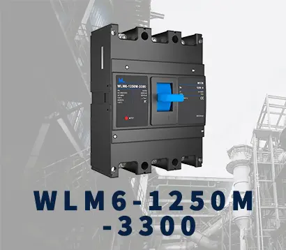 WLM6-1250A-3300 3P/4P
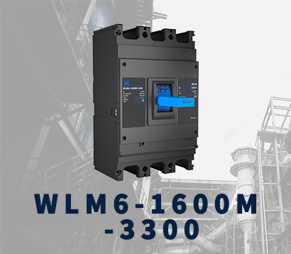 WLM6-1600A-3300 3P/4P
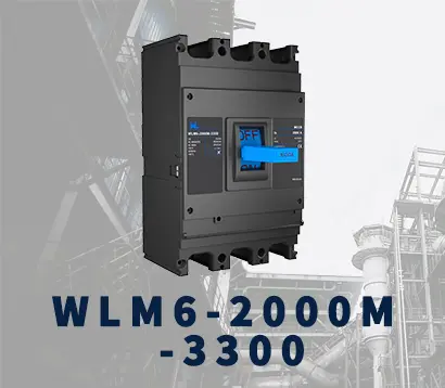 WLM6-2000A 3P/4P
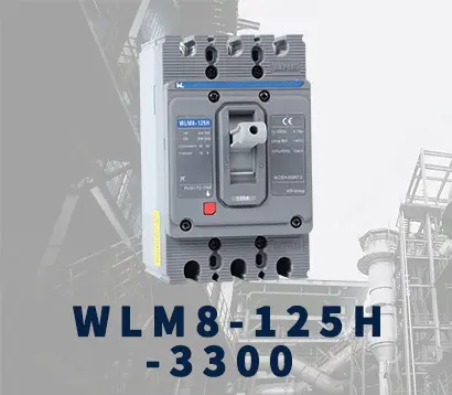 WLM8-125H-3300
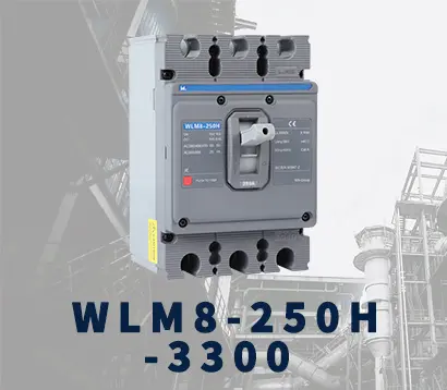 WLM8-250H-3300
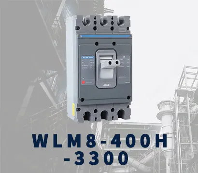 WLM8-400H-3300
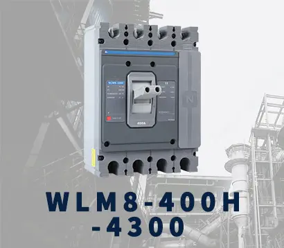 WLM8-400H-4300
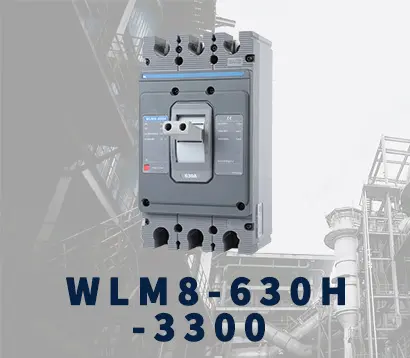 WLM8-630H-3300
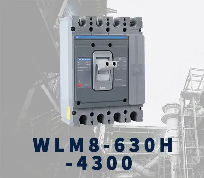 WLM8-630H-4300
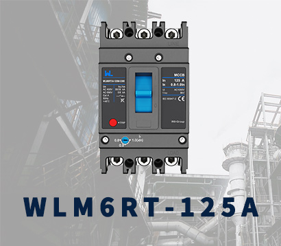 WLM6RT-125A
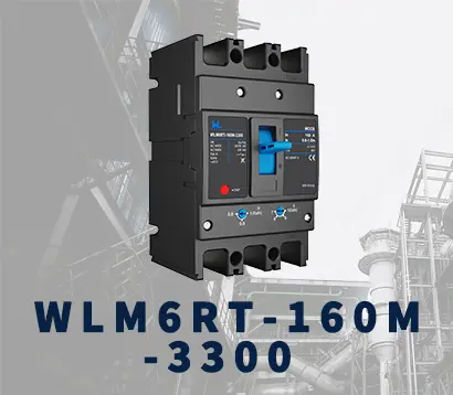 WLM6RT-160A
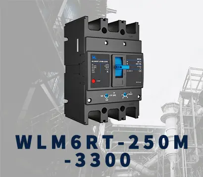 WLM6RT-250A
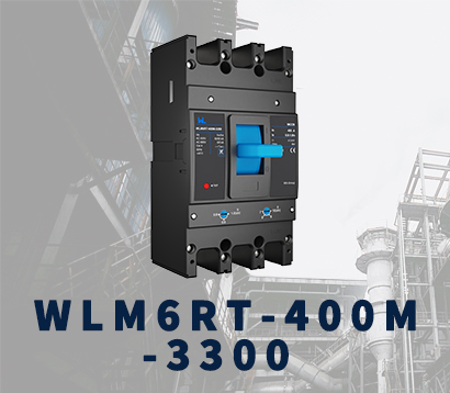 WLM6RT-400A
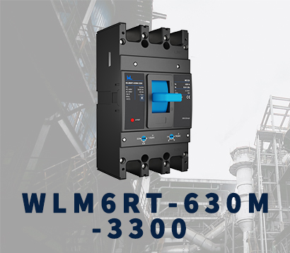 WLM6RT-630A
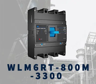 WLM6RT-800A
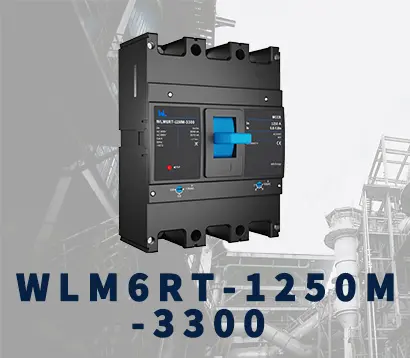 WLM6RT-1250A
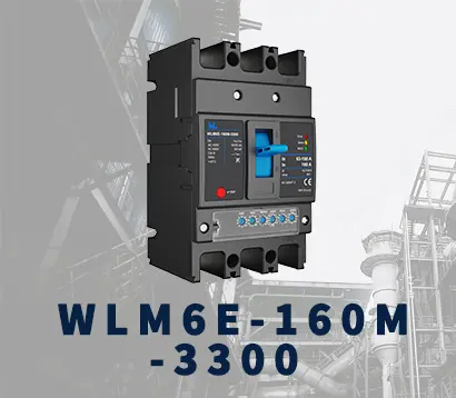 WLM6E-160A-3300 3P
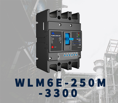 WLM6E-250A-3300
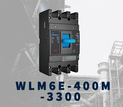 WLM6E-400A-3300 3P/4P
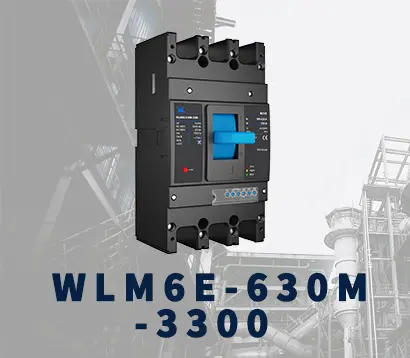 WLM6E-630A-3300
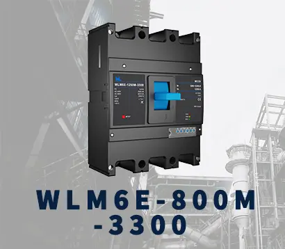 WLM6E-800A-3300 3P/4P
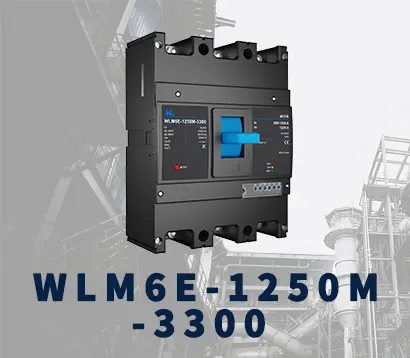 WLM6E-1250A-3300
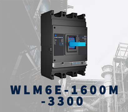 WLM6E-1600-3300 3P/4P
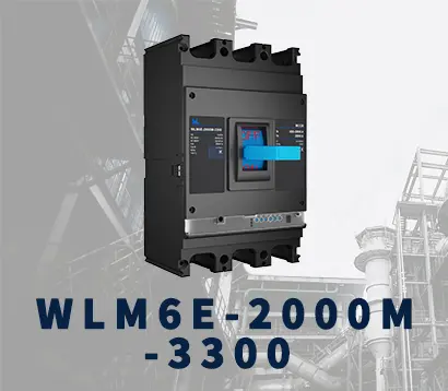 WLM6E-2000A-3300 3P/4P
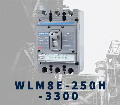 WLM8E-250H-3300
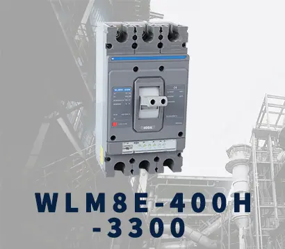 WLM8E-400H-3300
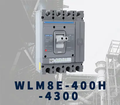 WLM8E-400H-4300
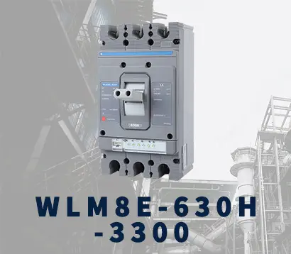 WLM8E-630H-3300
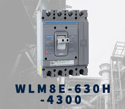 WLM8E-630H-4300
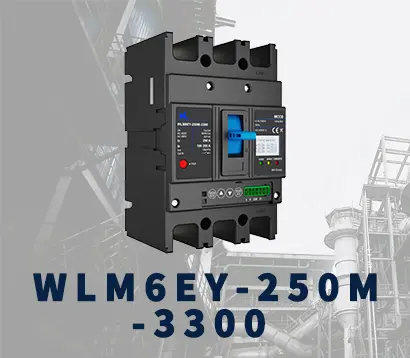 WLM6EY-250-3300 3P/4P
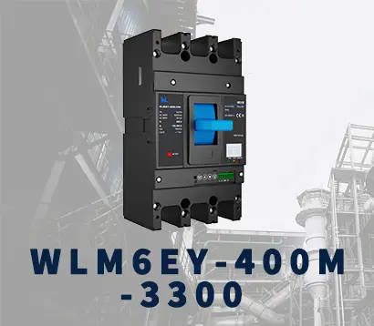 WLM6EY-400 3P/4P
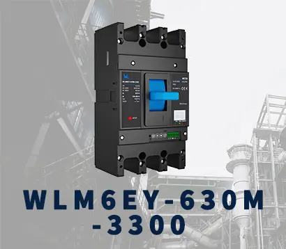 WLM6EY-630 3P/4P
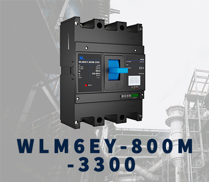 WLM6EY-800A 3P/4P
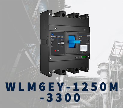 WLM6EY-1250A 3P/4P
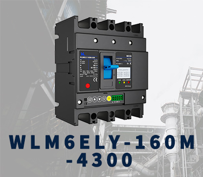 WLM6ELY-160A
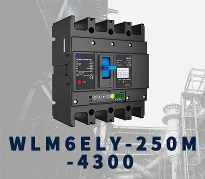 WLM6ELY-250A
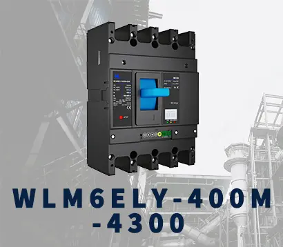 WLM6ELY-400A
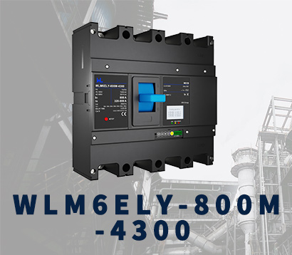 WLM6ELY-800A
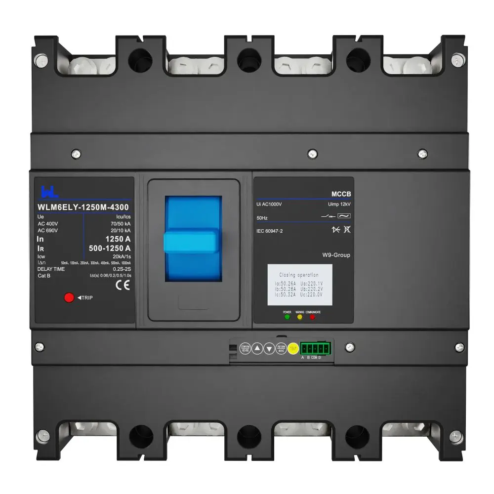 WLM6ELY-1250A
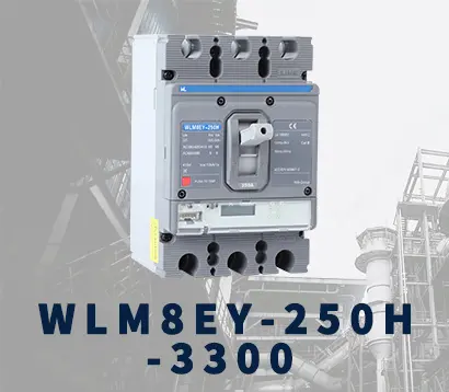 WLM8EY-250H-3300
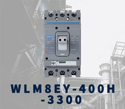 WLM8EY-400H-3300
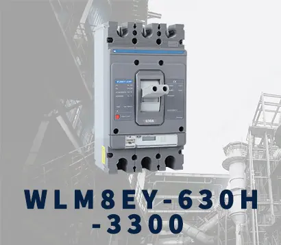 WLM8EY-630H-3300
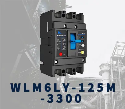 WLM6LY-125A
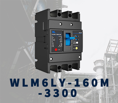 WLM6L-160A
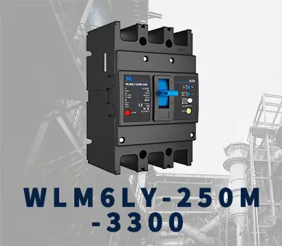 WLM6LY-250A
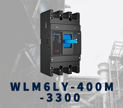 WLM6LY-400A
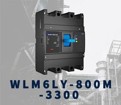 WLM6LY-800A
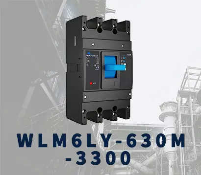 WLM6LY-630A
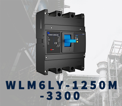 WLM6LY-1250A
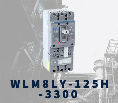 WLM8LY-125H-3300
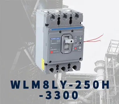 WLM8LY-250H-3300
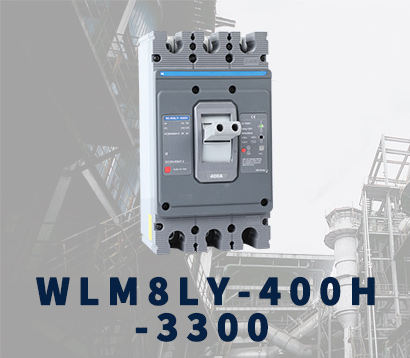 WLM8LY-400H-3300
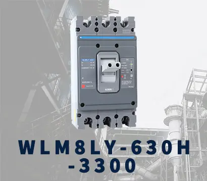 WLM8LY-630H-3300
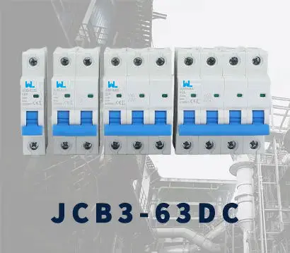 JCB3-63DC
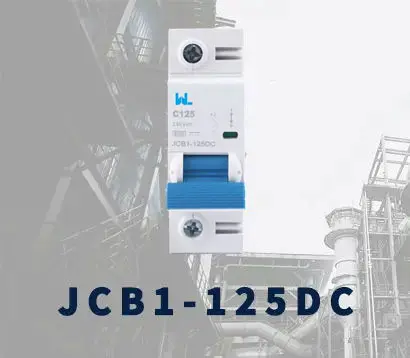 JCB1-125DC
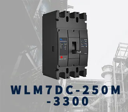 WLM7DC-250A-2300 2P/3P
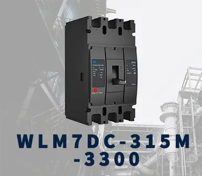 WLM7DC-315A-3300 2P/3P
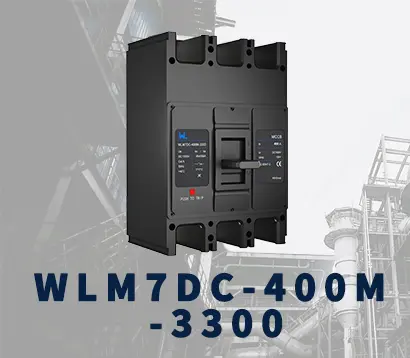 WLM7DC-400A-2300 2P/3P
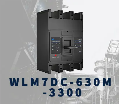 WLM7DC-630A-3300 3P
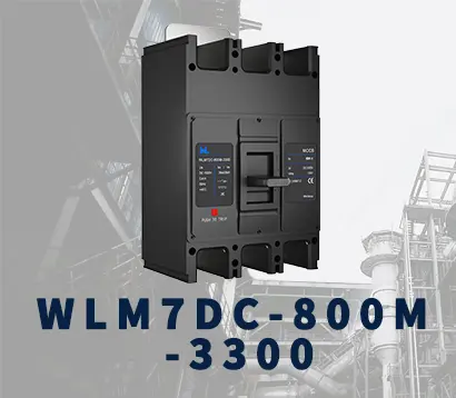 WLM7DC-800A-2300 2P/3P
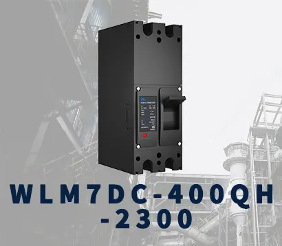 WLM7DC-400A 2300
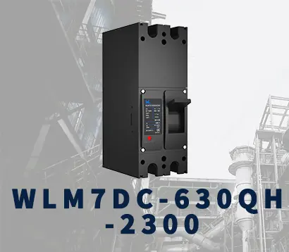 WLM7DC-630A-2300 2P
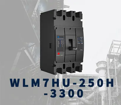 WLM7HU-250-3300 3P
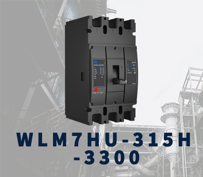 WLM7HU-315-3300 3P
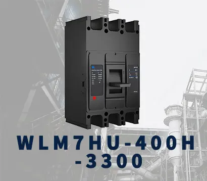 WLM7HU-400-3300 3P
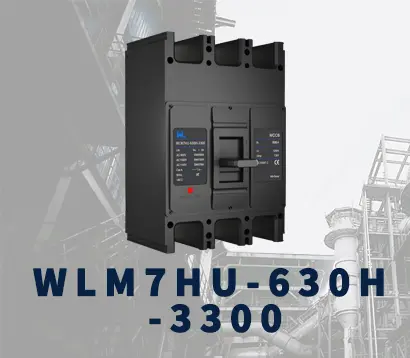 WLM7HU-630-3300 3P
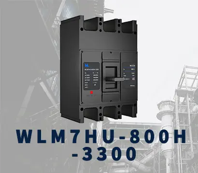 WLM7HU-800-3300 3P
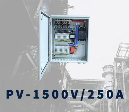 PV-1500V/250A
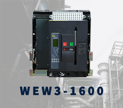 WEW3-1600
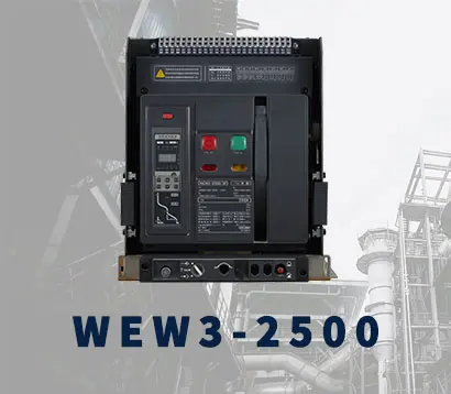 WEW3-2500
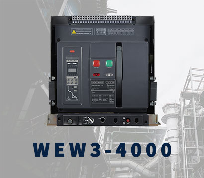 WEW3-4000
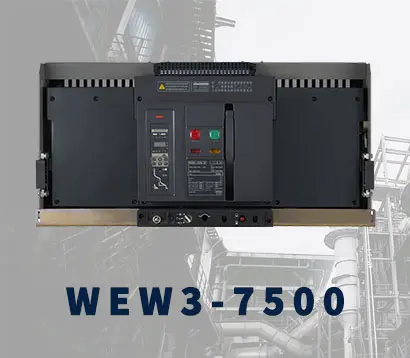 WEW3-7500