How to Choose the Right Electronic MCCB?
Choosing the right Electronic Mccb begins with the circuit, not the product catalogue. A breaker must match voltage, current, fault level, enclosure conditions, and coordination requirements. The International Energy Agency’s Electricity 2024 report projects global electricity demand growth of about 4% in 2024 and an average annual increase of 3.3% through 2026. More electrical loads mean greater pressure on distribution systems and protection equipment.
The selection process should examine rated current, interrupting capacity, adjustable trip settings, and overload protection. IEC 60947-2 provides the primary performance framework for low-voltage circuit-breakers, including industrial MCCBs. Electronic trip units can improve measurement accuracy and selectivity, especially where motors, transformers, or variable-speed drives create changing load profiles. However, electronic functions do not correct poor system design. A 250 A breaker may be unsuitable if the installation fault current exceeds its tested breaking capacity.
The installation environment matters too. Dust, heat, humidity, vibration, and limited cabinet space can change practical performance. A field engineer should compare short-circuit calculations, cable ampacity, and upstream-downstream coordination before approval. Manufacturer test reports and certification records deserve careful review. Some published market reports forecast strong growth for electronic protection devices, but definitions and regional samples vary. That limitation is easy to overlook. Therefore, this guide focuses on verifiable specifications and application evidence rather than market enthusiasm. The final choice should protect people, equipment, and continuity of service without creating unnecessary cost or complexity. Mistakes remain possible, so commissioning tests and periodic inspection should never be treated as optional.
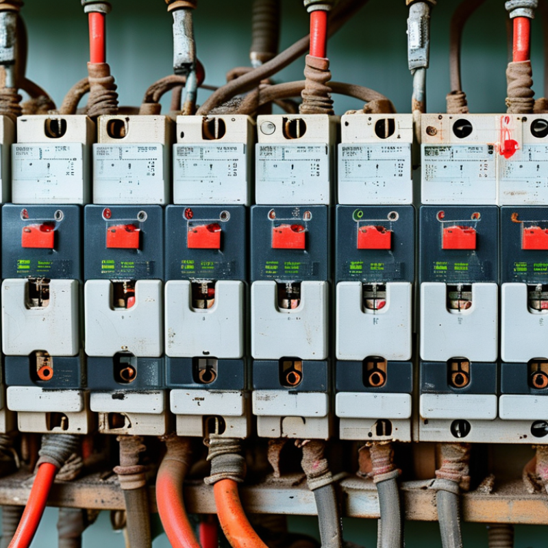
Define the Role and Operating Conditions of the Electronic MCCB
How to Choose the Right Electronic MCCB?
Define the Role and Operating Conditions of the Electronic MCCB
An electronic MCCB should match its role, not only the panel’s rated current. It may protect a feeder, motor, transformer, generator, or sensitive control circuit. Each application produces different starting currents, fault levels, and coordination needs. The IEA Electricity 2024 report projects global electricity demand to grow by about 3.4% annually from 2024 to 2026. This growth makes accurate protection settings increasingly important.
Check the expected load, prospective short-circuit current, ambient temperature, altitude, enclosure ventilation, and switching frequency. Electronic trip units allow adjustable long-time, short-time, instantaneous, and ground-fault protection. However, flexibility can create mistakes. A high instantaneous setting may prevent nuisance trips, but it can also delay fault interruption. Coordination with upstream and downstream devices must be tested, not simply assumed. IEC 60947-2 provides the key performance framework for low-voltage circuit breakers. EIA load forecasts also indicate continuing pressure on distribution systems, especially during peak demand.
Tips: Record the actual operating current during commissioning. Compare it with design calculations. Test trip functions under controlled conditions. Review settings after major load changes. A small detail matters: cable temperature can rise inside a crowded enclosure. I would avoid copying settings from another panel. Similar ratings do not guarantee similar operating conditions. Also, check whether the electronic trip unit remains reliable during voltage dips, harmonics, and communication loss. Decisions should follow measured site data, manufacturer-independent calculations, and qualified inspection.
Calculate Required Current, Voltage, and Interrupting Capacity
Choosing the right electronic MCCB starts with measured load data, not a catalog guess. Record motor ratings, duty cycles, power factor, efficiency, and ambient temperature. For a three-phase load, calculate current as I = P ÷ (√3 × V × PF × η). For single-phase equipment, use I = P ÷ (V × PF × η). Where NEC 2023 applies, size conductors and protection for continuous loads at 125% of their calculated value. Do not simply multiply the nameplate current.
Voltage must match the distribution system. A 400 V panel needs an MCCB rated for at least 400 V, with the correct number of poles and switching arrangement. Check frequency and grounding conditions too. Small details matter. IEC 60947-2:2024 separates ultimate breaking capacity, Icu, from service breaking capacity, Ics. Ics is often a percentage of Icu, so confirm both values in the test documentation.
Interrupting capacity must exceed the available fault current at the installation point. IEEE 3002.3-2018 provides accepted short-circuit calculation methods. For example, a panel with 18 kA available fault current needs an MCCB with a tested rating above 18 kA at its operating voltage. Use the utility fault-current report, transformer impedance, conductor length, and upstream protection data. I have seen designs fail here. The calculation looked correct, but the transformer data was outdated. Recheck it. Thermal settings, instantaneous pickup, and coordination should then be verified against actual motor starting currents and measured site conditions.
Compare Protection, Trip, and Adjustment Functions
How to Choose the Right Electronic MCCB?
When selecting an electronic MCCB, compare protection, trip, and adjustment functions before checking frame size. A thermal-magnetic breaker may cover basic overloads, but an electronic trip unit offers more precise settings.
Long-time protection manages sustained overloads.
Short-time protection handles temporary fault currents.
Instantaneous protection reacts to severe faults.
Ground-fault protection can reduce equipment damage when correctly coordinated.
Adjustment matters in real installations. Long-time pickup should match the conductor’s allowable ampacity, not simply the breaker’s maximum rating. Short-time delay can improve selectivity between upstream and downstream devices. However, excessive delay increases thermal and arc energy exposure.
The International Electrotechnical Commission’s IEC 60947-2 standard defines key requirements for low-voltage circuit breakers, including rated performance and verification tests. Field engineers should also review manufacturer test curves and coordination studies.
Small details matter.
ESFI’s workplace electrical safety data reported 126 electrical fatalities in 2022, showing why fault protection deserves careful review. NFPA 70B emphasizes documented electrical maintenance, inspection, and testing practices. Yet adjustment settings are often copied from older projects without checking changed loads. That is a weak habit.
I have found that a slightly lower instantaneous setting may improve protection, but it can also cause nuisance tripping during motor starting. Test the actual system, record each setting, and reassess after major load changes. Reliable selection balances protection speed, system continuity, and verified field conditions.
Check Installation, Coordination, and Safety Requirements
How to Choose the Right Electronic MCCB?
Check Installation, Coordination, and Safety Requirements
Choosing an electronic MCCB begins with the installation, not the catalogue. Record the system voltage, available fault current, ambient temperature, and conductor size. Check whether the enclosure is dusty, damp, or crowded. A breaker rated for a clean control room may perform differently inside a hot workshop panel. Leave enough space for cable bending and heat dissipation. Small details matter.
Review the trip unit settings against the cable’s continuous current and short-circuit rating. Long-time, short-time, instantaneous, and ground-fault functions should match the system design. Coordination with upstream and downstream protective devices is equally important. A downstream fault should disconnect the smallest affected section. Use time-current curves, not guesswork. I have seen neat drawings fail because actual cable lengths changed the fault level. Recheck the field conditions.
Safety requirements must include isolation, arc-flash risk assessment, suitable personal protective equipment, and clear operating labels. Confirm that technicians can test, reset, and inspect the MCCB without reaching across live parts. Follow applicable electrical codes and the equipment manufacturer’s verified installation instructions. Testing should include torque checks, insulation verification, trip-unit configuration, and functional operation. Keep test records.
Do not rely on factory settings. They may not fit your network. A final review by a qualified electrical professional can reveal overlooked coordination problems, especially in generator-fed or multi-source systems. Even experienced teams miss something occasionally. That is why commissioning should be deliberate, documented, and open to correction.
| Selection Dimension | Typical Requirement or Example | What to Verify Before Selection | Safety and Coordination Consideration |
|---|---|---|---|
| Electrical System | Low-voltage AC distribution system, commonly up to 1,000 V AC | Confirm the system voltage, frequency, earthing arrangement, and whether the circuit is single-phase or three-phase. | Use an MCCB with a voltage rating equal to or higher than the system voltage and suitable insulation performance. |
| Number of Poles | 2-pole for single-phase circuits; 3-pole or 4-pole for three-phase circuits | Check whether the neutral conductor must be switched and whether the installation requires simultaneous disconnection of all live conductors. | For four-pole devices, verify the neutral-pole arrangement and switching sequence required by the electrical design. |
| Rated Current | Select a rating above the calculated continuous load, such as 160 A for a design current near 140 A | Calculate demand current, continuous load, ambient temperature, enclosure temperature, cable ampacity, and any derating factors. | The breaker rating must not exceed the allowable ampacity of the protected conductor after applicable correction factors. |
| Continuous Load | Apply the applicable code requirement for continuous loads; many designs use 125% of the continuous portion | Separate continuous and non-continuous loads, including HVAC, battery chargers, pumps, and process equipment. | Set or select the long-time pickup so that the conductor and equipment remain protected during sustained loading. |
| Interrupting Capacity | Choose an interrupting rating equal to or greater than the available prospective short-circuit current at the installation point | Obtain the calculated fault current for the specific bus or panel location, not only the utility transformer rating. | A breaker with insufficient interrupting capacity may fail to safely clear a fault and can create severe arc-flash and fire hazards. |
| Electronic Trip Unit | Common functions include long-time, short-time, instantaneous, and ground-fault protection | Confirm the required adjustment ranges, measurement accuracy, alarm contacts, trip indication, and communication functions. | Disable or adjust functions only when permitted by the protection study and the applicable installation rules. |
| Long-Time Protection | Protects conductors and equipment against prolonged overloads | Match the long-time pickup and delay to the conductor ampacity, transformer inrush, motor starting, and load profile. | A setting that is too low may cause nuisance trips; a setting that is too high may allow conductor overheating. |
| Short-Time Protection | Provides delayed clearing for short-circuit currents when selective coordination is required | Review the short-time pickup and delay against downstream breaker curves and the available fault current. | Use short-time delay only when the equipment short-circuit rating and arc-flash assessment support it. |
| Instantaneous Protection | Clears high-magnitude faults with minimal intentional delay | Check the instantaneous pickup against transformer inrush, motor starting current, and downstream device settings. | Keeping instantaneous protection active can reduce fault-clearing time, but may interfere with selective coordination. |
| Ground-Fault Protection | Required or recommended for certain services and larger systems, depending on local electrical rules | Verify system grounding, sensor arrangement, pickup level, time delay, and compatibility with downstream ground-fault devices. | Ground-fault protection must be tested and coordinated to reduce shock, fire, and equipment damage risks. |
| Selective Coordination | The downstream protective device should clear a fault before the upstream MCCB trips whenever feasible | Compare time-current curves, manufacturer-tested combinations, short-circuit ratings, and actual trip settings. | Do not rely only on ampere ratings; coordination depends on the full protection characteristics across the fault-current range. |
| Cascading or Series Rating | May be used only where the combination is evaluated and permitted by the applicable standards | Confirm that the upstream and downstream devices have a documented tested or engineered series-rating relationship. | Do not combine unrelated breakers simply because the upstream device has a higher interrupting rating. |
| Installation Environment | Indoor or outdoor location, enclosure type, ambient temperature, humidity, dust, and corrosive exposure | Check enclosure protection, ventilation, altitude correction, temperature derating, clearance, and accessibility. | Install the MCCB in an enclosure suitable for the environment and maintain the required working space. |
| Cable and Busbar Connection | Terminals must accept the conductor material, size, number of conductors, and termination method | Verify terminal torque, conductor bending space, busbar dimensions, lug compatibility, and temperature rating. | Loose or improperly sized terminations can cause overheating, arcing, and premature failure. |
| Motor and Transformer Loads | Allow for inrush and starting current while maintaining overload and short-circuit protection | Review starting duration, locked-rotor current, transformer energization current, and the equipment manufacturer's protection requirements. | Use appropriate time delays without compromising the required protection of conductors and connected equipment. |
| Breaking and Making Duty | The MCCB must be suitable for the expected fault duty and switching application | Check short-circuit ratings, utilization category, switching frequency, and whether the breaker is used for isolation. | Isolation functions and switching duties must comply with the applicable equipment and installation standards. |
| Testing and Maintenance | Periodic inspection, torque verification, functional testing, and trip-unit testing according to the maintenance plan | Confirm test access, event records, trip indication, insulation condition, and maintenance intervals. | De-energize and apply lockout/tagout procedures before maintenance unless a documented energized-work procedure is required. |
| Final Selection Decision | Accept only when electrical ratings, installation conditions, coordination, and safety requirements are all satisfied | Document the load calculation, fault-current study, coordination review, trip settings, installation checks, and inspection results. | Have the final design and settings reviewed by a qualified electrical professional. |
Evaluate Standards, Reliability, Maintenance, and Total Cost
How to Choose the Right Electronic MCCB?
Standards should be checked before comparing prices. IEC 60947-2 defines key requirements for molded-case circuit breakers, including rated short-circuit capacity and verification tests. Check both Icu and Ics values, not only the maximum interrupting rating. The breaker must match the installation’s fault level, voltage, frequency, and coordination study. Local certification requirements still matter. A datasheet alone is not enough.
Reliability depends on more than trip accuracy. Look for stable electronic sensing, clear overload settings, self-diagnostic functions, and event recording. These features help technicians understand a trip beside a noisy motor panel. Uptime Institute’s 2024 Annual Outage Analysis reported that 54% of respondents experienced an outage costing over $100,000. That figure covers data centers, not every facility. Still, it shows why dependable protection deserves serious attention. Field experience suggests that poor coordination often causes unnecessary shutdowns.
Maintenance should be practical. NFPA 70B-2023 emphasizes documented electrical maintenance programs, inspection, and testing. Choose an MCCB with accessible test points, replaceable accessories, and readable status indicators. Record trip settings after commissioning. Recheck them after major load changes. Total cost includes installation labor, testing time, spare components, energy losses, and downtime exposure. A cheaper breaker may become expensive after one difficult fault investigation. That is easy to miss. A lifecycle worksheet may reveal the difference, although its assumptions should be challenged every year.
Related Posts
-
Top Microprocessor Based MCCB Options for Global Buyers?
-
What is a Microprocessor Based MCCB and Its Benefits for Buyers?
-
Top 5 Microprocessor Based MCCB for Global Buyers?
-

How to Choose the Right Electronic MCCB for Optimal Circuit Protection and Efficiency
-
What is a Thermal Magnetic Circuit Breaker and How Does It Work?
-
How to Choose the Right Electric Main Breaker for Your Needs?

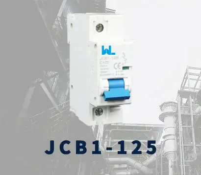
JCB1-125
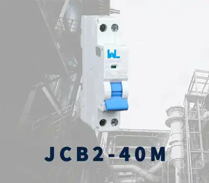
JCB2-40M
JCB3-63DC
JCB3-80H
JCB3-80M
JCBH-125
JC125-4P
JCMX
JCSD
JCOF
JCMX1-125
JCOF1-125
JCSD1-125
JCR3HM
JCRD2-125
JCRD4-125
JCRB2-100
JC3RH-2P
JC3RH-S
JC3RH-B
JC3RH-BS
JCR2-63
JCR1-40
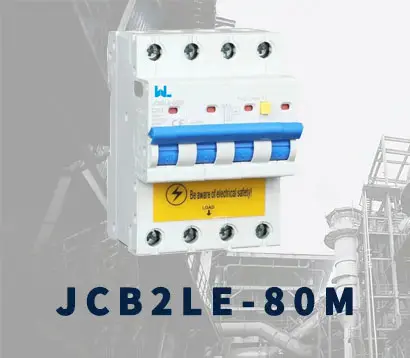
JCB2LE-80M
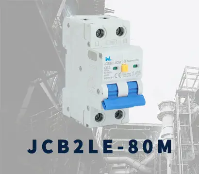
JCB2LE-80M
JCB2LE-80M
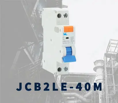
JCB2LE-40M
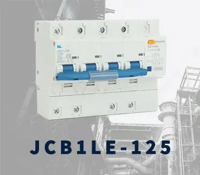
JCB1LE-125
JCB3LM-80
JCH2-125
JCH2-125
CJX2
CJ19
JCMCU
JCHA
JCSD-40
JCSD-60
JCSP-40
JCSP-60
JCSPV
WEW1-1000
WEW1-1600
WEW1-2000
WEW1-3200
WEW1-4000
WEW1-6300
DC6-125
AX-400-1250
AXAL-400-1250A
AL-400-1250
DC3-160
AXS-400-1250A
SHT-125-160
UVT-125-160A
P-250A-3P-A
400-3P/4P terminal cover
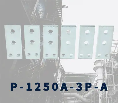
1250-3Pmccb accessories busbar
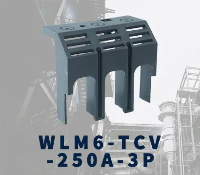
250-3P terminal conver
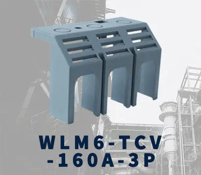
WLM6-TCV-160A-3P
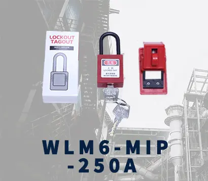
WLM6-MIP-250A
WLM6-125A-3300 3P/4P
WLM6-160A-3300 3P/4P
WLM6-250A-3300 3P/4P
WLM6-400A-3300 3P/4P
WLM6-630A-3300 3P/4P
WLM6-800A-3300 3P/4P
WLM6-1250A-3300 3P/4P
WLM6-1600A-3300 3P/4P
WLM6-2000A 3P/4P
WLM8-125H-3300
WLM8-250H-3300
WLM8-400H-3300
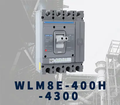
WLM8-400H-4300
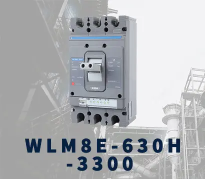
WLM8-630H-3300
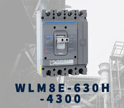
WLM8-630H-4300
WLM6RT-125A
WLM6RT-160A
WLM6RT-250A
WLM6RT-400A
WLM6RT-630A
WLM6RT-800A
WLM6RT-1250A
WLM6E-160A-3300 3P
WLM6E-250A-3300
WLM6E-400A-3300 3P/4P
WLM6E-630A-3300
WLM6E-800A-3300 3P/4P
WLM6E-1250A-3300
WLM6E-1600-3300 3P/4P
WLM6E-2000A-3300 3P/4P
WLM8E-250H-3300
WLM8E-400H-3300
WLM8E-400H-4300
WLM8E-630H-3300
WLM8E-630H-4300
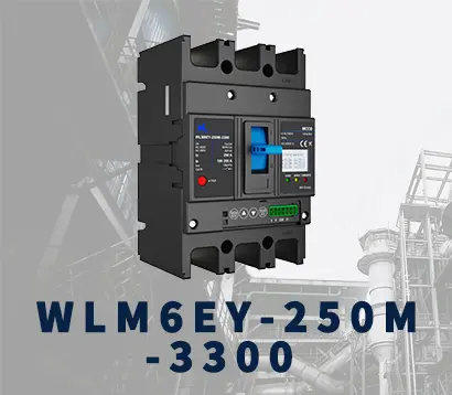
WLM6EY-250-3300 3P/4P
WLM6EY-400 3P/4P
WLM6EY-630 3P/4P
WLM6EY-800A 3P/4P
WLM6EY-1250A 3P/4P
WLM6ELY-160A
WLM6ELY-250A
WLM6ELY-400A
WLM6ELY-800A
WLM6ELY-1250A
WLM8EY-250H-3300
WLM8EY-400H-3300
WLM8EY-630H-3300
WLM6LY-125A
WLM6L-160A
WLM6LY-250A
WLM6LY-400A
WLM6LY-800A
WLM6LY-630A
WLM6LY-1250A
WLM8LY-125H-3300
WLM8LY-250H-3300
WLM8LY-400H-3300
WLM8LY-630H-3300
JCB3-63DC
JCB1-125DC
WLM7DC-250A-2300 2P/3P
WLM7DC-315A-3300 2P/3P
WLM7DC-400A-2300 2P/3P
WLM7DC-630A-3300 3P
WLM7DC-800A-2300 2P/3P
WLM7DC-400A 2300
WLM7DC-630A-2300 2P
WLM7HU-250-3300 3P
WLM7HU-315-3300 3P
WLM7HU-400-3300 3P
WLM7HU-630-3300 3P
WLM7HU-800-3300 3P
PV-1500V/250A
WEW3-1600
WEW3-2500
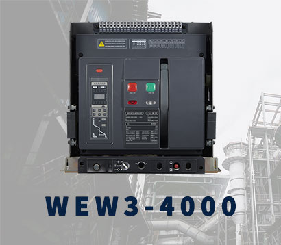
WEW3-4000
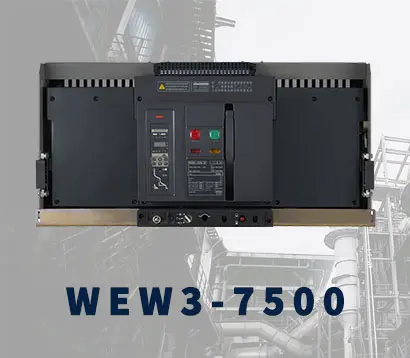
WEW3-7500