How to Choose a DC MCCB for Solar Systems?
Solar capacity is expanding quickly, and DC protection deserves more than a quick look at the current rating. IRENA’s Renewable Capacity Statistics 2024 reports 1,419 GW of installed solar capacity worldwide at the end of 2023, with about 346 GW added that year. Behind each installation are conductors, modules, and switching devices exposed to sustained direct current. A Dc Mccb must interrupt that current safely, not merely fit inside the panel.
John Wiles, a well-known photovoltaic safety specialist, has emphasized through his published guidance that protection must suit the actual circuit and its fault conditions. That is a practical principle, not a substitute for checking the device’s documentation. Compare the system’s maximum DC voltage, continuous current, and prospective short-circuit current with the breaker’s ratings. Then check its DC interrupting capacity, pole configuration, polarity requirements, and permitted wiring direction. IEC 60947-2 is a relevant reference for circuit-breaker requirements, but the product’s DC rating and manufacturer instructions still matter.
Small details count. A breaker in a hot combiner box may not carry its marked current under actual conditions. Cable size, ambient temperature, and the number of connected strings can change the selection. A neat datasheet can still leave a blind spot. Do not assume an AC breaker can interrupt DC safely; the arc behaves differently. This guide explains how to compare ratings, verify compatibility, and avoid common selection errors. Real installations vary, and that is exactly why a careful review matters.

Understanding the Role of a DC MCCB in a Solar System
How to Choose a DC MCCB for Solar Systems?
Understanding the Role of a DC MCCB in a Solar System
A DC MCCB protects a solar circuit from overloads and short circuits, and can provide a means of isolation when correctly rated. Unlike AC, DC current has no natural zero crossing to help extinguish an electrical arc. That matters. The breaker must be designed for DC interruption at the system’s operating voltage, not merely selected by its current rating.
Its role depends on where it sits in the system. A breaker on a PV array circuit must account for the array’s maximum open-circuit voltage, including increases in cold weather. A battery circuit can deliver much higher fault current than a PV string. Check the breaker’s interrupting capacity, pole arrangement, polarity requirements, and coordination with cables and connected equipment. Not interchangeable. Even a careful design can overlook the actual fault-current source.
Tips: Compare the breaker’s DC ratings with the system’s worst-case conditions, not its typical sunny-day readings. Follow the device maker’s wiring instructions, and have a qualified solar professional verify the selection. A rating that looks sufficient on paper may not fit the circuit.
How to Choose a DC MCCB for a Solar System
Example: cold-weather correction increases the PV string’s open-circuit voltage (Voc), which the MCCB’s DC voltage rating must accommodate.
This illustrative calculation assumes 10 modules in series, a module Voc of 50 V at 25°C, and a Voc temperature coefficient of −0.30%/°C. At −10°C, the estimated string Voc is 552.5 V. Select an MCCB with a DC voltage rating at least as high as the site’s maximum temperature-corrected array Voc. Choose its current rating and DC breaking capacity using the array design, applicable electrical codes, conductor ampacity, and the manufacturer’s specifications.
Assessing System Voltage and Maximum Operating Current
A DC MCCB must be rated above the array’s maximum voltage, not just its normal operating voltage. Calculate the cold-weather open-circuit voltage by applying the module’s temperature coefficient to its Voc, then multiplying by the number of modules in series. Cold mornings matter: module voltage rises as temperature falls. IEC 62548-1:2023 sets out requirements for PV array design, including voltage considerations. Check the breaker’s DC voltage rating and interrupting capacity at that voltage. A rating printed for AC service alone is not enough.
Current needs equal care. Add the short-circuit current of parallel strings, then apply the sizing factors required by the applicable electrical code and equipment instructions. Do not size from the inverter’s AC output; it can miss the array-side current conditions. Also check continuous-current limits and any temperature derating inside a hot, sealed enclosure. That margin matters. IEA PVPS’s Trends in Photovoltaic Applications 2024 reports about 1.6 TW of cumulative global PV capacity by the end of 2023, underscoring the scale of modern deployment. Yet even a small rooftop array needs project-specific calculations. A spreadsheet can make the answer look certain while hiding an incorrect cold-temperature input. Recheck the module data, site minimum temperature, and string layout before selecting the MCCB.
How to Choose a DC MCCB for Solar Systems? - Assessing System Voltage and Maximum Operating Current
| Example PV Circuit |
Maximum Cold-Corrected PV Voltage |
Maximum Continuous Operating Current |
Minimum MCCB DC Voltage Rating |
Illustrative MCCB Trip Rating |
Key Selection Check |
| 600 V DC array circuit |
580 V DC |
32 A |
At least 600 V DC |
40 A |
Confirm the breaker’s DC rating applies to the required pole configuration and circuit polarity. |
| 1,000 V DC array circuit |
980 V DC |
125 A |
At least 1,000 V DC |
160 A |
Verify the breaker can interrupt the calculated prospective DC fault current at the system voltage. |
| 1,500 V DC array circuit |
1,450 V DC |
250 A |
At least 1,500 V DC |
315 A |
Use a breaker specifically rated for the required high-voltage DC application; confirm series-pole wiring instructions. |
These examples are illustrative, not final equipment specifications. Calculate maximum PV voltage using the module’s open-circuit voltage and the lowest expected cell temperature. Select the MCCB voltage rating to meet or exceed that corrected voltage, and choose its current rating and trip settings in accordance with applicable electrical codes, conductor ampacity, system design, and manufacturer instructions. The DC interrupting rating must be at least the calculated prospective fault current.
Matching Interrupting Capacity to Solar Fault Conditions
A DC MCCB must interrupt the highest prospective fault current at its installation point—not merely match the array’s normal current. Check its interrupting rating at the system’s actual DC voltage; an AC rating cannot be assumed to apply. IEC 60909-0 provides methods for calculating short-circuit currents, while UL 489B addresses breakers for photovoltaic circuits. Use the device’s tested DC rating and permitted pole configuration.
For a practical estimate, twelve parallel strings with a module short-circuit current of 13.5 A produce 162 A before applicable correction factors. NEC 690.8 uses a 125% factor for PV circuit-current calculations, but that figure alone does not establish the fault current a breaker must interrupt. Include possible backfeed from parallel strings, batteries, and other sources. A battery can change the fault picture sharply. A tidy spreadsheet can still miss a source.
Tips: Gather module Isc, string count, battery fault-current data, cable lengths, and the MCCB’s DC rating. Confirm voltage, polarity, and series-pole wiring against its instructions. Check the DC rating. If source data is uncertain, ask a qualified engineer to verify the calculation; guessing here is not a shortcut.
Choosing Pole Configuration and Protection Features
A DC MCCB’s pole configuration must match the array’s voltage and grounding arrangement. A two-pole breaker may switch both conductors, but it is not automatically suitable for every PV circuit. Check whether the system is grounded or floating, and follow the breaker’s wiring diagram. Some DC breakers require poles to be connected in series to reach their rated voltage. Do not assume that arrangement is optional. Small details matter.
Compare the breaker’s rated operational voltage with the maximum array voltage, including cold-weather increases. Confirm its interrupting capacity can handle the available DC fault current. DC arcs are persistent, so a breaker designed only for AC is not a substitute. Also check polarity markings and connection direction; some models are polarity-sensitive. A clear label helps during installation, but the diagram is decisive.
Protection features should suit the conductors and inverter, not just the nominal current. Thermal-magnetic trips can address overloads and short circuits, while adjustable settings may help coordinate upstream and downstream devices. Verify cable ampacity, ambient-temperature derating, and the inverter’s requirements together. Ground-fault detection may be separate, so inspect the system design rather than expecting one breaker to cover everything. A tidy specification sheet can still leave a gap. Recheck the full protection scheme before selecting the device.
Checking Standards, Installation Conditions, and System Compatibility
A DC MCCB should match the array’s maximum corrected open-circuit voltage, expected operating current, and prospective fault current. IEC 60947-2 covers circuit-breaker requirements; IEC 62548-1 addresses photovoltaic array design. Check the device’s DC ratings and permitted pole connections against its datasheet, not just its current label. A neat nameplate match can still mislead. IEA PVPS’s Snapshot of Global PV Markets 2024 estimates that 447 GW of PV capacity was installed in 2023, bringing global capacity to about 1,418 GW. That growth makes consistent protection selection important, but each array still needs a project-specific check.
Installation conditions can change a breaker’s usable rating. Review ambient temperature inside the enclosure, altitude, orientation, terminal temperature limits, and required clearances. Confirm cable size, conductor type, and terminal torque against the installation instructions. Check the whole path. In a cold climate, low cell temperature can raise module open-circuit voltage; in a hot cabinet, thermal derating can reduce the breaker’s current capacity. Verify that the interrupting rating covers the calculated fault current at the actual DC voltage. Also confirm whether the system’s grounding arrangement and pole configuration suit the selected device. I would recheck these details after the enclosure layout is fixed; drawings rarely capture every heat source or cable bend. When system data is incomplete, pause and obtain it rather than treating an assumed value as a final design input.

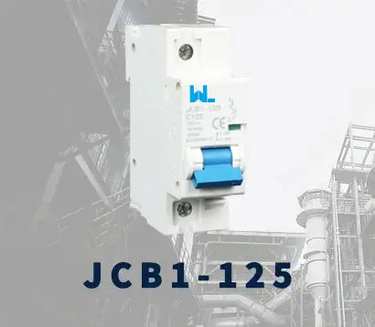 JCB1-125
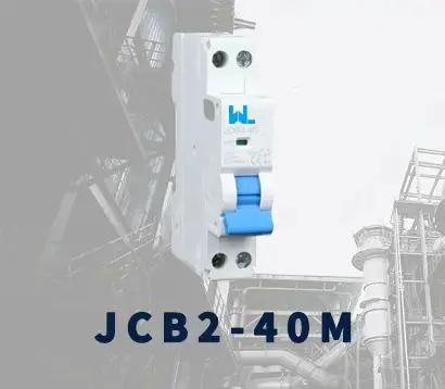 JCB2-40M
 JCB3-63DC
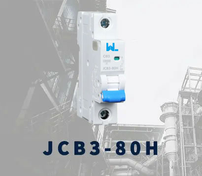 JCB3-80H
 JCB3-80M
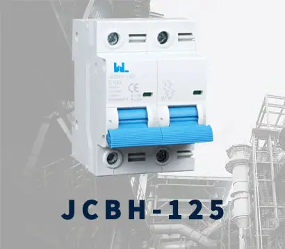 JCBH-125
 JC80-2P
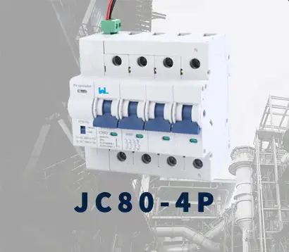 JC80-4P
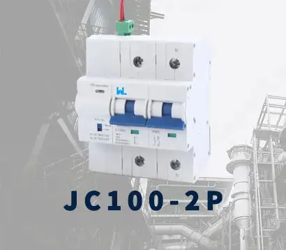 JC125-2P
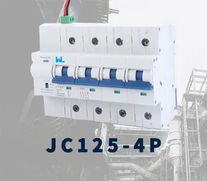 JC125-4P
 JCMX
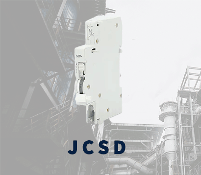 JCSD
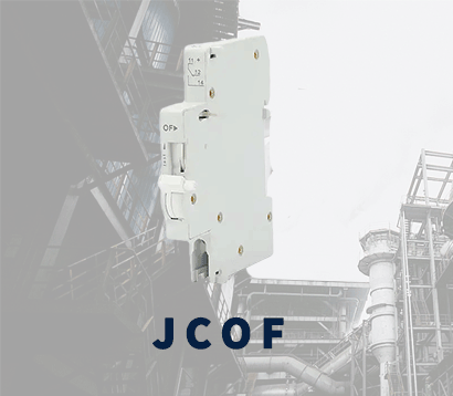 JCOF
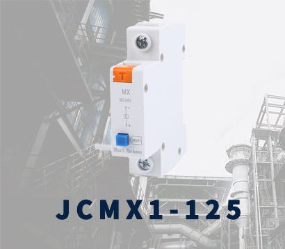 JCMX1-125
 JCOF1-125
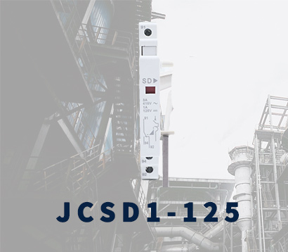 JCSD1-125
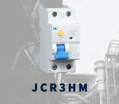 JCR3HM
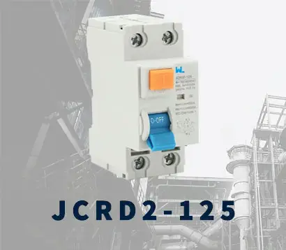 JCRD2-125
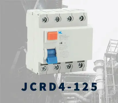 JCRD4-125
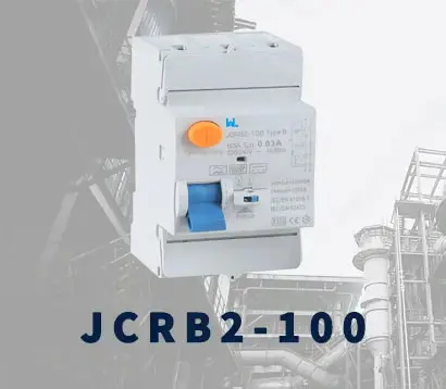 JCRB2-100
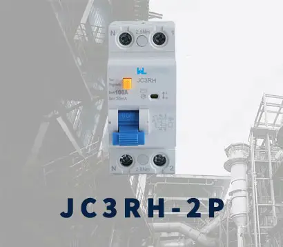 JC3RH-2P
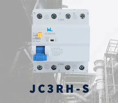 JC3RH-S
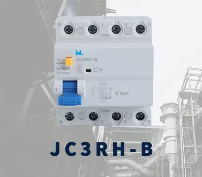 JC3RH-B
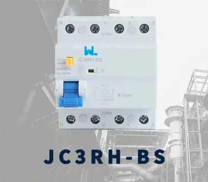 JC3RH-BS
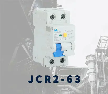 JCR2-63
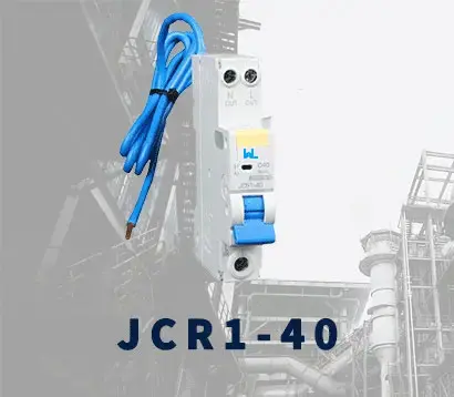 JCR1-40
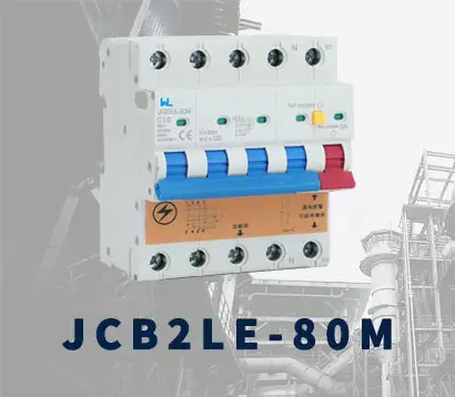 JCB2LE-80M
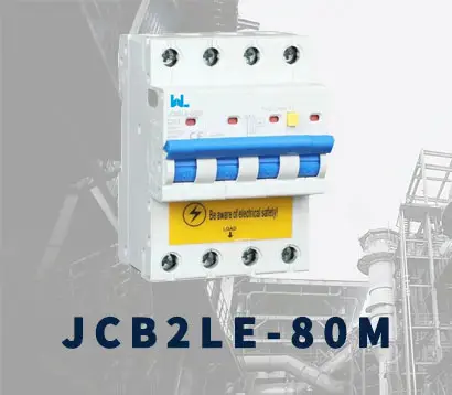 JCB2LE-80M
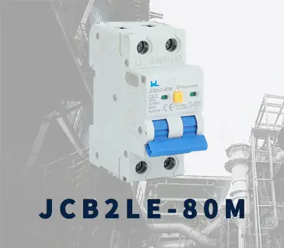 JCB2LE-80M
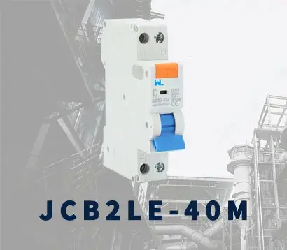 JCB2LE-40M
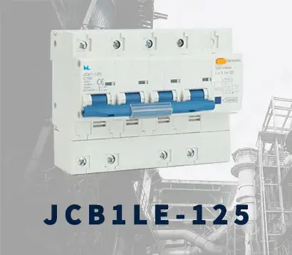 JCB1LE-125
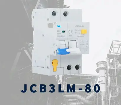 JCB3LM-80
 JCH2-125
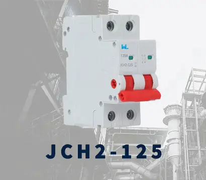 JCH2-125
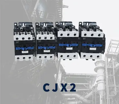 CJX2
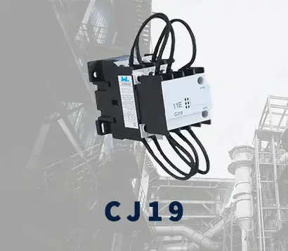 CJ19
 JCMCU
 JCHA
 JCSD-40
 JCSD-60
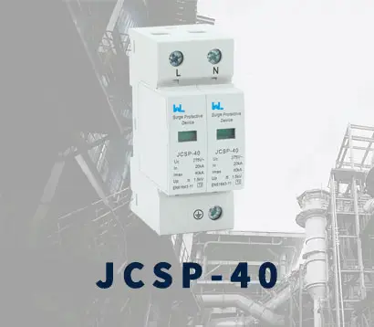 JCSP-40
 JCSP-60
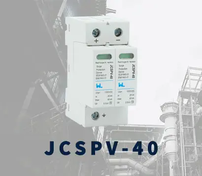 JCSPV
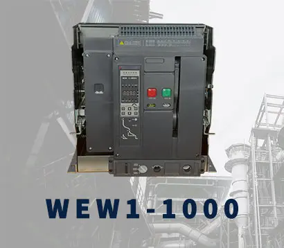 WEW1-1000
 WEW1-1600
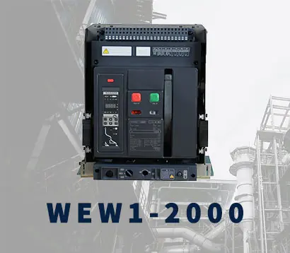 WEW1-2000
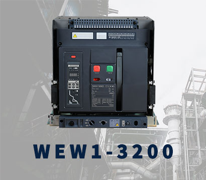 WEW1-3200
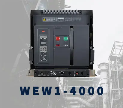 WEW1-4000
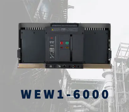 WEW1-6300
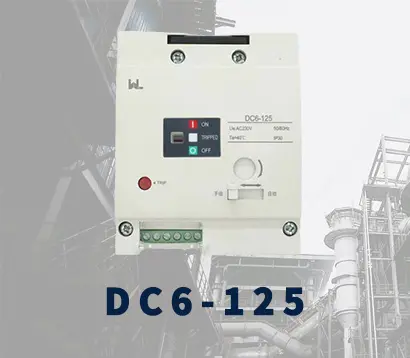 DC6-125
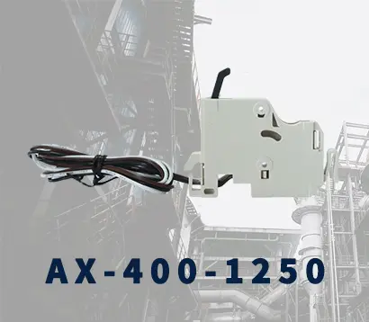 AX-400-1250
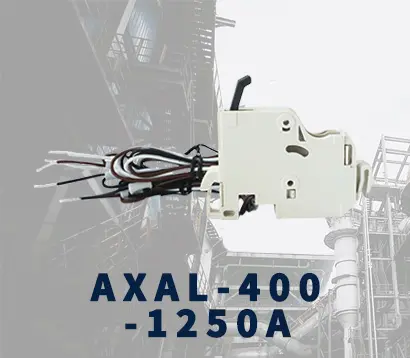 AXAL-400-1250A
 AL-400-1250
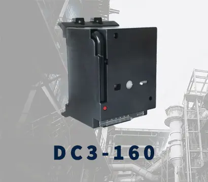 DC3-160
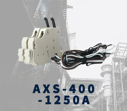 AXS-400-1250A
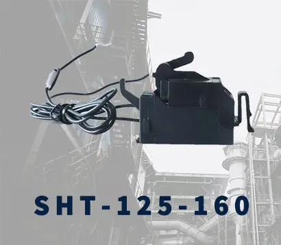 SHT-125-160
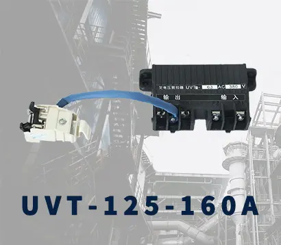 UVT-125-160A
 P-250A-3P-A
 400-3P/4P terminal cover
 1250-3Pmccb accessories busbar
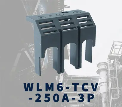 250-3P terminal conver
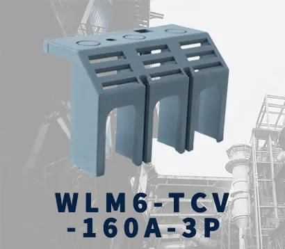 WLM6-TCV-160A-3P
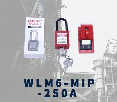 WLM6-MIP-250A
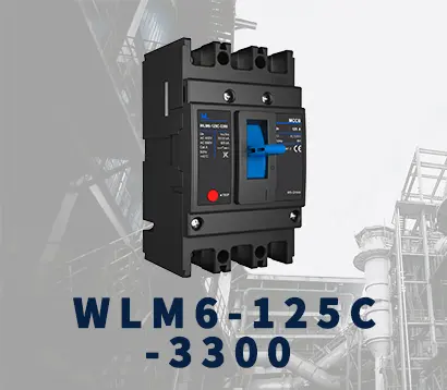 WLM6-125A-3300 3P/4P
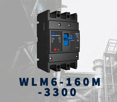 WLM6-160A-3300 3P/4P
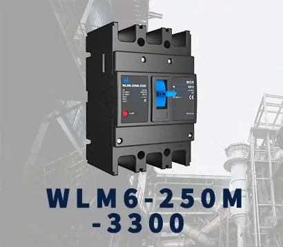 WLM6-250A-3300 3P/4P
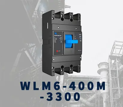 WLM6-400A-3300 3P/4P
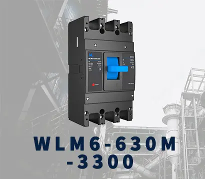 WLM6-630A-3300 3P/4P
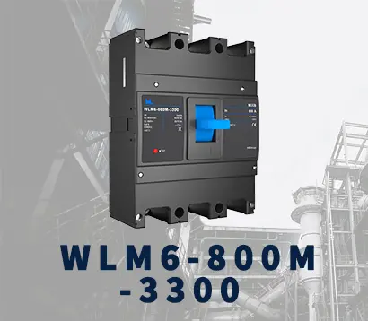 WLM6-800A-3300 3P/4P
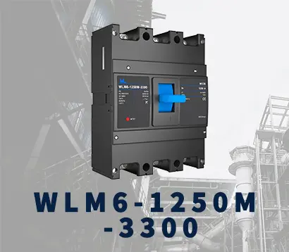 WLM6-1250A-3300 3P/4P
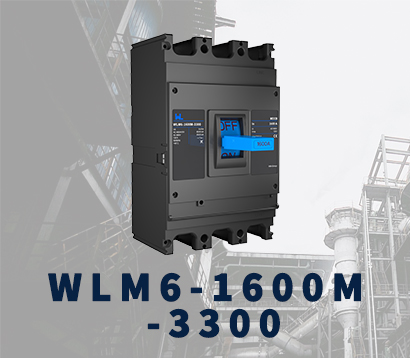 WLM6-1600A-3300 3P/4P
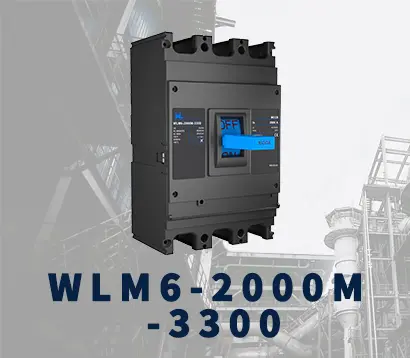 WLM6-2000A 3P/4P
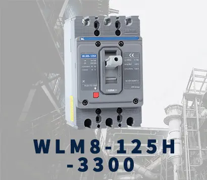 WLM8-125H-3300
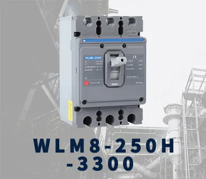 WLM8-250H-3300
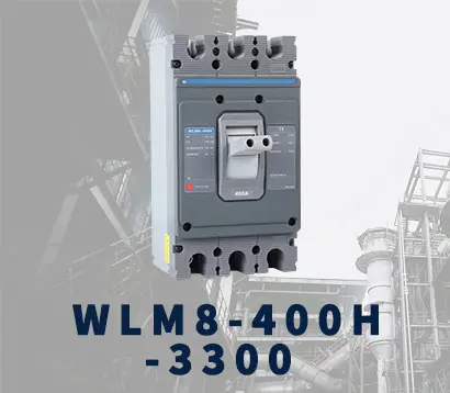 WLM8-400H-3300
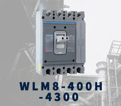 WLM8-400H-4300
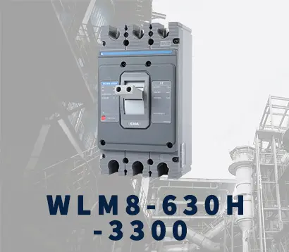 WLM8-630H-3300
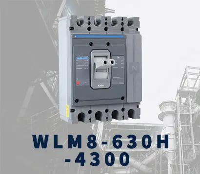 WLM8-630H-4300
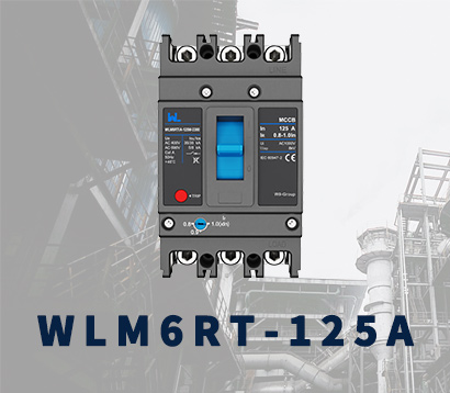 WLM6RT-125A
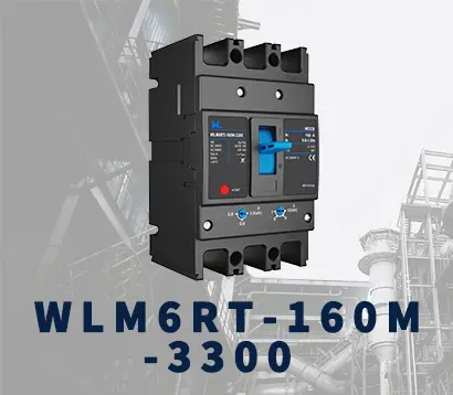 WLM6RT-160A
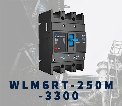 WLM6RT-250A
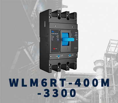 WLM6RT-400A
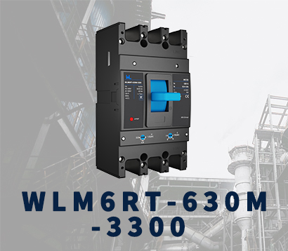 WLM6RT-630A
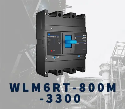 WLM6RT-800A
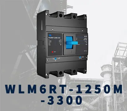 WLM6RT-1250A
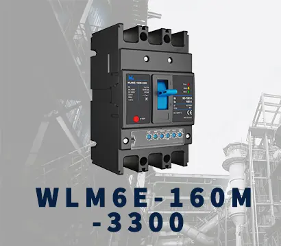 WLM6E-160A-3300 3P
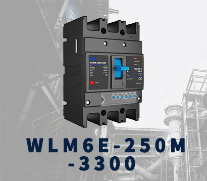 WLM6E-250A-3300
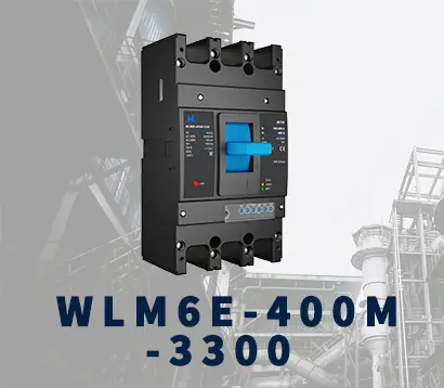 WLM6E-400A-3300 3P/4P
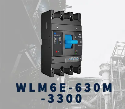 WLM6E-630A-3300
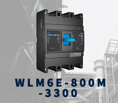 WLM6E-800A-3300 3P/4P
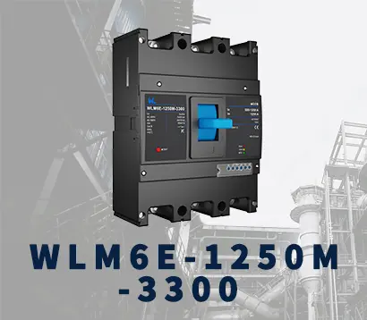 WLM6E-1250A-3300
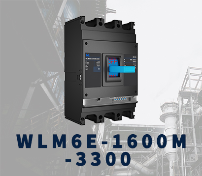 WLM6E-1600-3300 3P/4P
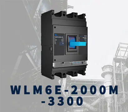 WLM6E-2000A-3300 3P/4P
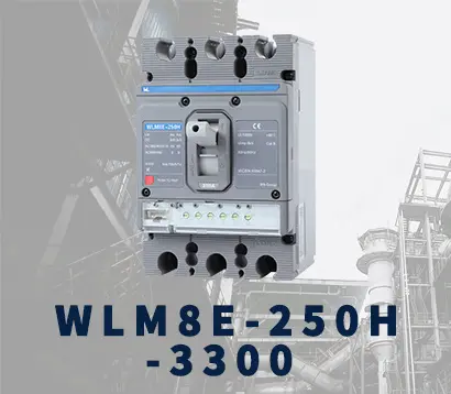 WLM8E-250H-3300
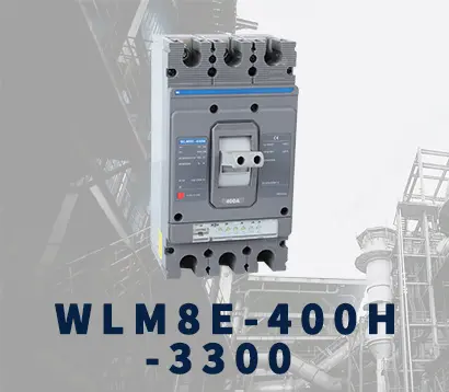 WLM8E-400H-3300
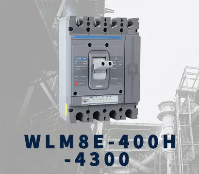 WLM8E-400H-4300
 WLM8E-630H-3300
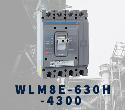 WLM8E-630H-4300
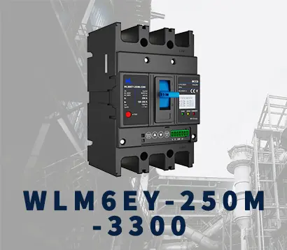 WLM6EY-250-3300 3P/4P
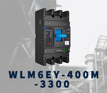 WLM6EY-400 3P/4P
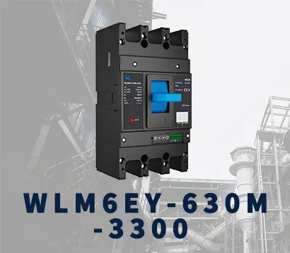 WLM6EY-630 3P/4P
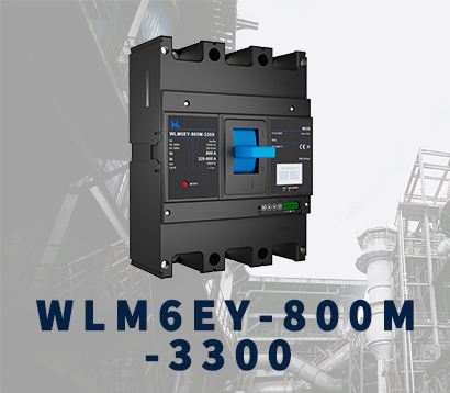 WLM6EY-800A 3P/4P
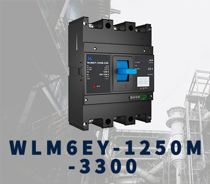 WLM6EY-1250A 3P/4P
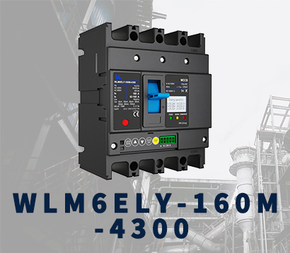 WLM6ELY-160A
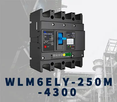 WLM6ELY-250A
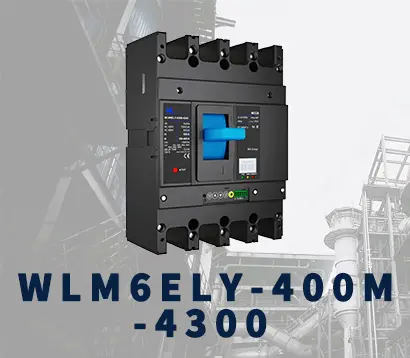 WLM6ELY-400A
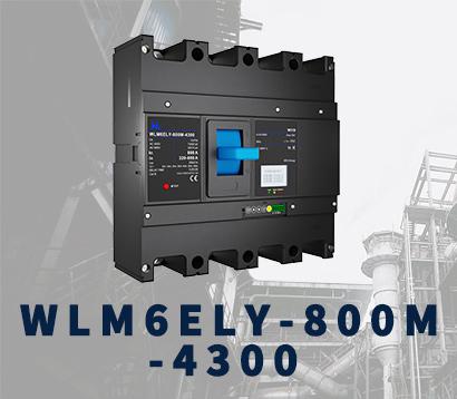 WLM6ELY-800A
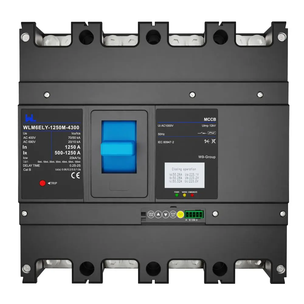 WLM6ELY-1250A
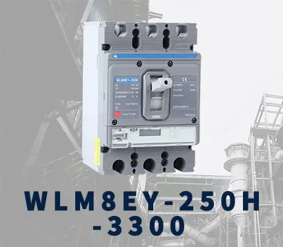 WLM8EY-250H-3300
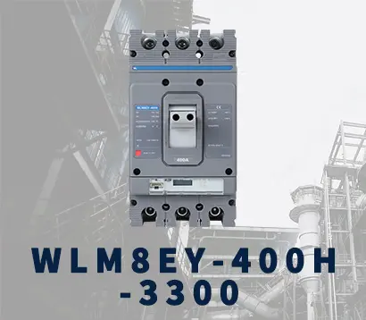 WLM8EY-400H-3300
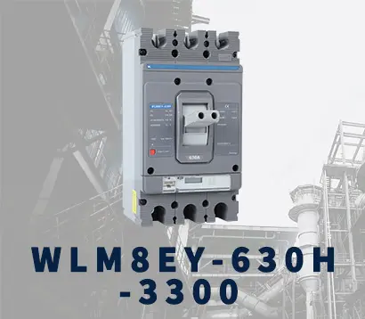 WLM8EY-630H-3300
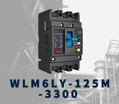 WLM6LY-125A
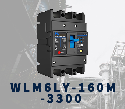 WLM6L-160A
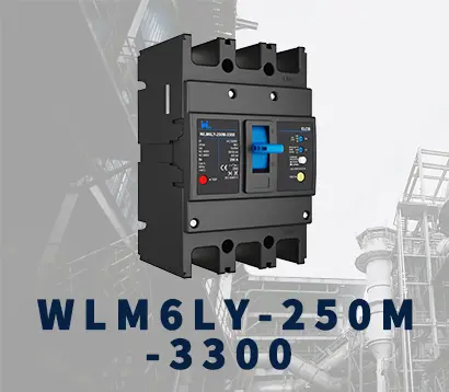 WLM6LY-250A
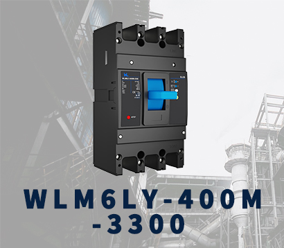 WLM6LY-400A
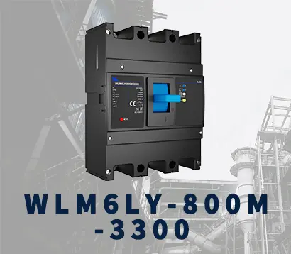 WLM6LY-800A
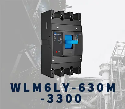 WLM6LY-630A
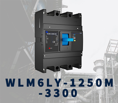 WLM6LY-1250A
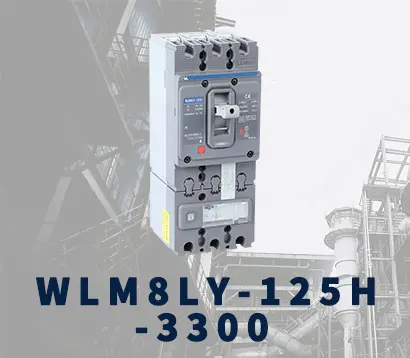 WLM8LY-125H-3300
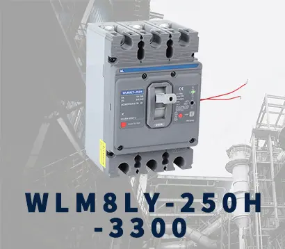 WLM8LY-250H-3300
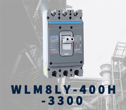 WLM8LY-400H-3300
 WLM8LY-630H-3300
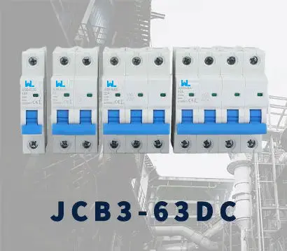 JCB3-63DC
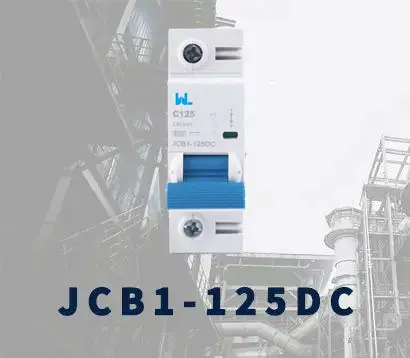 JCB1-125DC
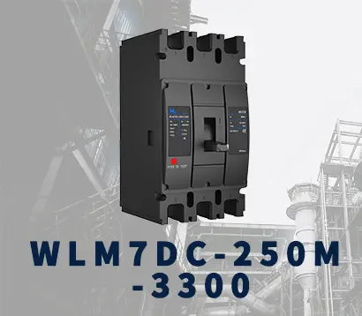 WLM7DC-250A-2300 2P/3P
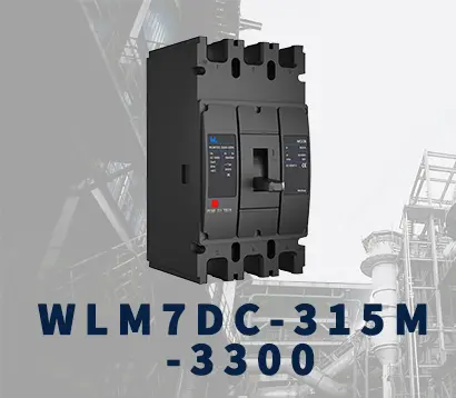 WLM7DC-315A-3300 2P/3P
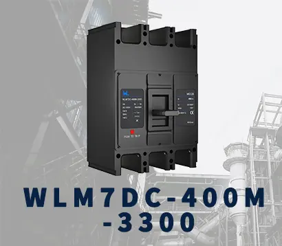 WLM7DC-400A-2300 2P/3P
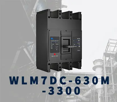 WLM7DC-630A-3300 3P
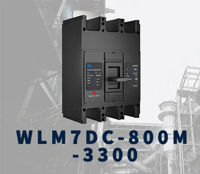 WLM7DC-800A-2300 2P/3P
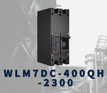 WLM7DC-400A 2300
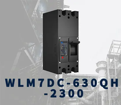 WLM7DC-630A-2300 2P
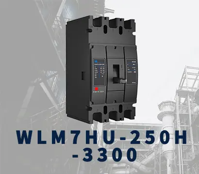 WLM7HU-250-3300 3P
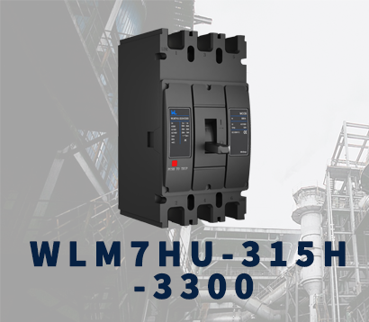 WLM7HU-315-3300 3P
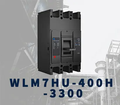 WLM7HU-400-3300 3P
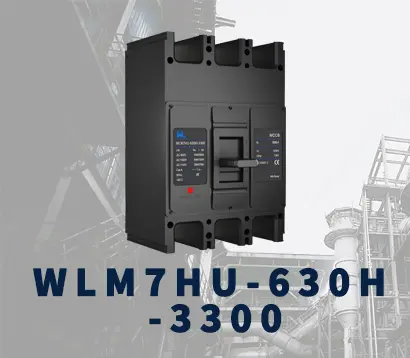 WLM7HU-630-3300 3P
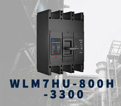 WLM7HU-800-3300 3P
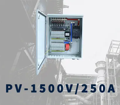 PV-1500V/250A
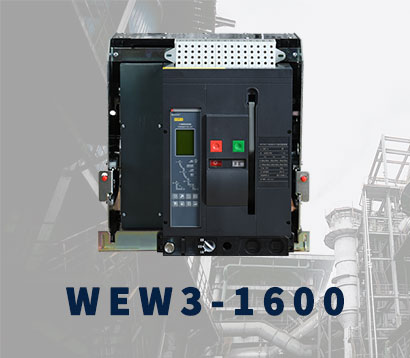 WEW3-1600
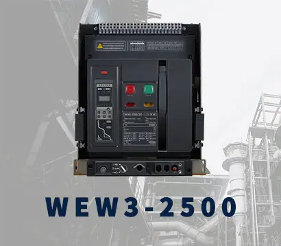 WEW3-2500
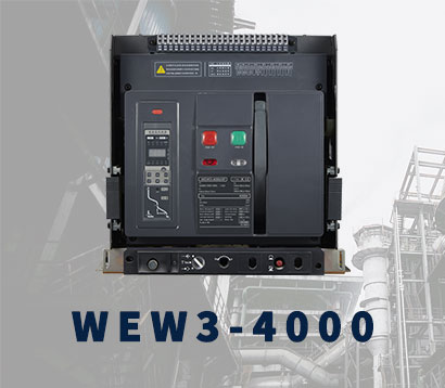 WEW3-4000
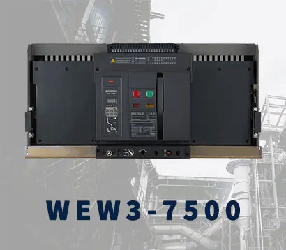 WEW3-7500